 LK Automation Limited
Multi axis positioning controller.
Coaxial data communication line function.
Program capacity: Max 60K step.
Input / output points: 1920 points.
PLC commonly used in memory are EPROM, EEPROM and with lithium battery powered RAM.
General micro and small PLC storage capacity is fixed, between 1~2KB AJ65SBT2B-64RD3.
How much memory is occupied by a usser application is related to many factors,
Such as I/O points, control requirements, computing processing, program structure, etc..
So it can only be roughly estimated before the program is designed AJ65SBT2B-64RD3. Program memory capacity: 8k.
Input / output points: maximum 256 points.
A scan cycle of PLC must pass through three stages: input sampling, program execution and output refresh.
PLC in the input sampling phase: first of all, in order to scan the sequence of all existing input latches in the input terminal of the state or input data read,
And write it into the corresponding input status register,
Refresh the input, then close the input port, enter the program execution stage AJ65SBT2B-64RD3.
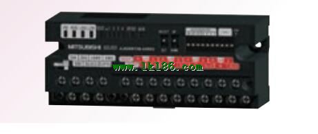
Screw, 2 piece type terminal
Temperature measuring resistor body input module MITSUBISHI AJ65SBT2B-64RD3.
Number of channels: 4 channels.
Number of stations: 1 stops.
Station type: remote equipment station.
MITSUBISHI PLC online debugging.
On-line debugging is the process that will through the simulation debugging to further carry on the on-line unification to adjust MITSUBISHI AJ65SBT2B-64RD3.
On-line debugging process should be step by step,
From MITSUBISHI PLC only connected to the input device, and then connect the output device, and then connect to the actual load and so on and so on step by step.
If you do not meet the requirements, the hardware and procedures for adjustment MITSUBISHI AJ65SBT2B-64RD3.
Usually only need to modify the part of the program can be.
MITSUBISHI PLC hardware implementation
Hardware implementation is mainly for the control cabinet and other hardware design and field construction.
Design control cabinet and the operating table and other parts of the electrical wiring diagram and wiring diagram.
Electrical interconnection diagram of each part of the design system.
According to the construction drawings of the site wiring, and carrry out a detailed inspection AJ65SBT2B-64RD3.
Because the program design and hardware implementation can be carried out at the same time,
So the design cycle of the MITSUBISHI PLC control system can be greatly reduced. Applicable model: A975/970/960GOT (-B).