 LK Automation Limited
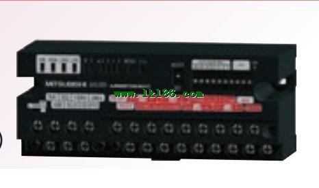
Input type: DC input, negative public end.
Input points: 8 points.
Enter the response time: 1.5ms the following.
Rated input voltage / current: DC24V/5mA.
Output form: transistor output, source.
Output points: 8 points.
OFF leakage current: 0.1mA.
Output protection function AJ65SBT2B-64AD.
Rated load voltage / current: DC24V/DC24V/0..1A.
External connection: 3 line /2 line type.
Sensor connector type (E-CON type).
Using industry standard E-CON type.
Simple wiring through sensor connector AJ65SBT2B-64AD.
When installing the module can choose to use the DIN guide rail or screw mounting.
3 wire sensor input.
Screw terminal table type.
High precision / high resolution / high speed 2 piece type terminal.
Voltage / current input module.
Number of channels: 4 channels AJ65SBT2B-64AD.
Number of stations: 1 stops.
Station type: remote equipment station.
MITSUBISHI PLC hardware implementation
Hardware implementation is mainly for the control cabinet and other hardware design and field construction.
Design control cabinet and the operating table and other parts of the electrical wiring diagram and wiring diagram MITSUBISHI AJ65SBT2B-64AD.
Electrical interconnection diagram of each part of the design system.
According to the construction drawings of the site wiring, and carry out a detailed inspection.
Because the program design and hardware implementation can be carried out at the same time,
So the design cycle of the MITSUBISHI PLC control system can be greatly reduced MITSUBISHI AJ65SBT2B-64AD.
MITSUBISHI PLC online debugging.
On-line debugging is the process that will through the simulation debugging to further carry on the on-line unification to adjust MITSUBISHI AJ65SBT2B-64AD.
On-line debugging process should be step by step,
From MITSUBISHI PLC only connected to the input device, and then connect the output device, and then connect to the actual load and so on and so on step by step.
If you do not meet the requirements, the hardware and procedures for adjustment.
Usually only need to modify the part of the program can be. A3VTS with additional floor.
Switch volume control is designed to,
According to the current input combination of the switch quantity and the history of the input sequence,
So that PLC generates the corresponding switching output,
In order to make the system work in a certain order.
So, sometimes also known as the order control.
And sequential control is divided into manual, semi-automatic or automatic.
And the control principle is decentralized, centralized and hybrid control three.
Each scanning process. Focus on the input signal sampling. Focus on the output signal to refresh.
Input refresh process. When the input port is closed,
Program in the implementation phase, the input end of a new state, the new state can not be read.
Only when the program is scanned, the new state is read.
A scan cycle is divided into the input sample, the program execution, the output refresh.
The contents of the component image register are changed with the change of the execution of the program.
The length of the scan cycle is determined by the three.
CPU the speed of executing instructions.
Time of instruction.
Instruction count.
Due to the adoption of centralized sampling.
Centralized output mode.
There exist input / output hysteresis phenomena, i.e., the input / output response delay.
System program memory for storing system proggram,
Including management procedures, monitoring procedures, as well as the user program to do the compiler to compile the process of interpretation AJ65SBT2B-64AD.
Read only memory. Manufacturers use, content can not be changed, power does not disappear.