 LK Automation Limited
Output points: 16 points.
Output voltage and current: DC24V/AC240V, 2A/1 point, 8A/1 common end.
Output response time: 12ms.
8 point /1 a public side.
Output form: relay output.
40 point terminal station.
MITSUBISHI PLC protection and chain procedures.
Protection and chain is an indispensable part of the program, must be carefully considered AJJ65SBT-RPT.
It can avoid the control logic confusion caused by illegal operations.
MITSUBISHI PLC initialization procedure. After MITSUBISHI PLC on power, the general need to do some of the initial operation,
In order to start making necessary preparations, to avoid the wrong operation of the system AJ65SBT-RPT.
The main contents of the initialization program are: to some data area, counter and so on,
Data needed to restore some of the data area,
Set or reset some relays,
For some initial state display, etc AJ65SBT-RPT..
MITSUBISHI PLC program simulation debugging
The basic idea of program simulation debugging is,
In order to facilitate the form of simulation to generate the actual state of the scene,
Create the necessary environmental conditions for the operation of the program MITSUBISHI AJ65SBT-RPT.
Depending on the way the field signals are generated,
The simulation debugging has two forms of hardware simulation and software simulation. RS-232:1, RS-422/485:1.
Transmission speed: 0.3 ~ 19.2kpbs.
Computer connection function MITSUBISHI AJ65SBT-RPT.
So far the system''s hardware electrical circuit has been determined.
Printer / peripheral device connection, BASIC language function.
How to choose MITSUBISHI PLC.
MITSUBISHI PLC options include the choice of MITSUBISHI PLC models, capacity, I/O module, power, etc MITSUBISHI AJ65SBT-RPT..
MITSUBISHI PLC distribution I/O points and design MITSUBISHI PLC peripheral hardware circuit
Draw the I/O point of the PLC and the input / output device connection diagram or the corresponding table,
This part also can be carried out in second steps.
Design PLC peripheral hardware circuit.
Draw the electrical wiring diagram of the other parts of the system,
Including the main circuit and the control circuit does not enter the PLC, etc..
The electrical schematic diagram of the system composed of I/O PLC connection diagram and PLC peripheral electrical circuit diagram.
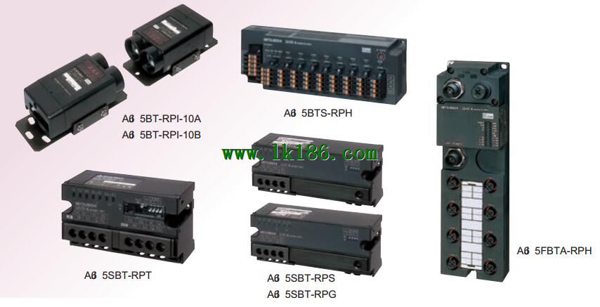
Description: the maximum number of connections: paragraph 10, can form a T type branch wiring.
Spare 5 products for different purposes.
Thin waterproof type relay hub.
Extension of star type wiring and main line length, waterproof structure.
Spring clip terminal type relay hub.
Star type wiring, length of the main line, spring clamping terminal table type.
Relay appliance (T branch) unit.
Exxtension of T type branch and trunk length AJ65SBT-RPT.
Relay unit in light.
In the presence of interference in the environment of the wiring, the length of the trunk line.
Relay unit in space light.
Communication between linear moving bodies.