 LK Automation Limited
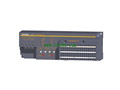
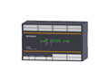
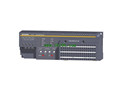
MITSUBISHI QS0J61BT12 Safety Application Guide QS0J61BT12 Manual
Product model: QS0J61BT12
Name: PLC
Brand: MITSUBISHI
Sort: Safety Application Guide
File language: English
Download link: MITSUBISHI QS0J61BT12 Safety Application Guide
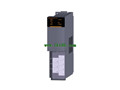
Output points: 4 points (select the source type + drain type), 2 points (select the source type + source).
Isolation mode: photoelectric coupling.
Rated input voltage: DC24V.
Security PLC (secure programmable system) refers to the self or external components or the implementation of the failure of the agency,
Can still respond to and promptly cut off the output of the programmable system QS0J61BT12 Safety Application Guide QS0J61BT12
Different from ordinary PLC, security PLC not only can provide the function of ordinary PLC,
Safe control function can be realized,
Meet the requirements of the ISO 13849-1 EN and IEC 61508 control system safety related component standards.
PLC security market mainstream has oilz (Pilz) PSS 3000, PSS 4000,
PSS 4000 in addition to the security process can also be processed outside the standard control procedures QS0J61BT12 Safety Application Guide.
All the components in the security PLC adopt the redundancy structure,
Two processor processing for cross detection,
The processing results of each processor are stored in their respective memory,
Output is only when the processing result is in full agreement,
If any inconsistency occurs during the process, the system is immediately shut down QS0J61BT12 Safety Application Guide. 8 channels.
Input: AC0~5A AC0~50A, CT, AC0~100 until AC0~600A.
Output: 0~10000.
18 point terminal.
Directly connected to the CT sensor, saving wiring and space of the CT input module.
Directly connected with CT sensor and programmable controller,
No need for external connection signal converter, etc..
Very accurate measurement results can be obtained by stable data transfer speed,
Then, load control and operation of the system and equipment are carried out, and the power supply system is managed and monitored.
Directly connect the CT sensor, saving wiring and space
In the case of no external signal converter, directly connected to the CT sensor.
A module can be used to measure up to 8 channels of alternating current, thereby reducing wiring time and cost.
Set the CT sensor type (input range) for each channel.
Through a module to select from AC0 ~ 5A to 600A ~ CT AC0 sensor.
Preventive maintenance can be carried out by detecting the peak current.
Peak current detection function
By detecting the peak current, the equipment can perform maintenance and troubleshooting.
Take the motor as an example, the load applied on the motor changes due to wear and damage of the gear,
Load current will suddennly change QS0J61BT12 Manual.
By detecting the transient peak current at this time, the fault of the equipment can be diagnosed.
Input signal error detection function
Can detect whether the CT input value is out of range (higher than the peak value)) QS0J61BT12 Manual.
Because the large current flow on the measurement object is beyond the range limit,
Therefore, the error of the measurement object can be monitored.
Last one:
MITSUBISHI QS001CPU Safety Application Guide
next one: MITSUBISHI QS90SR2SP-CC Safety Application Guide
next one: MITSUBISHI QS90SR2SP-CC Safety Application Guide
Related products
MITSUBISHI
Safety CC-Link system remote I/O module
QS0J65BTS2-4T
Output points: 4 points select the sour
MITSUBISHI
Safety CC-Link system remote I/O module
QS0J65BTB2-12DT
Input points: 8 points dual input, 16
MITSUBISHI
Safety CC-Link system remote I/O module
QS0J65BTS2-8D
Input points: 8 points dual input, 16
MITSUBISHI
Safety CC-Link system master module
QS0J61BT12
Speed of delivery: optional 156kps/625k