 LK Automation Limited
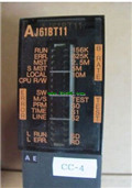
AJ61BT11 PDF catalog MITSUBISHI CC-Link module AJ61BT11 datasheet PDF datasheet
Product model: AJ61BT11
Name: CC-Link module
Brand: MITSUBISHI
Sort: PDF datasheet
File language: English
Download link: MITSUBISHI AJ61BT11 PDF datasheet
A pack of 20.
Applicable models:
AJ65SBTC - - - type remote I/O module.
AJ65VBTCU - - - type remote I/O module.
AJ65VBTCU- - type remote I/O module. Input points: 32 points.
Input voltage and current: 240V ~ 10mA AC100.
Input response time: 35ms.
16 point /1 a public side.
Output points: 24 points.
Output voltage: AC100 ~ 240V MITSUBISHI CC-Link module PDF datasheet.
OFF leakage current: 3mA.
Output response time: 0 AJ61BT115Hz+1ms.
Output type: bidirectional thyristor output.
8 point /1 a public side.
36 point terminal station.
With short circuit protection.
With the surge absorber.
Control solenoid valve required I/O points by the action principle of the solenoid valve can be known,
A single coil solenoid valve with PLC control to 2 input and 1 output,
A double coil solenoid valve requires 3 inputs and 2 outputs,
A button needs an input; a light sensitive switch needs 4 or 2 inputs,
A signal lamp needs 1 output, band switch,
Several bands are required for several inputs,
In general, a variety of position switches are required to take up 2 input points MITSUBISHI CC-Link module PDF datasheet.
MITSUBISHI PLC is the main product in the production of MITSUBISHI motor in Dalian MITSUBISHI CC-Link module PDF datasheet.
It uses a kind of programmable memory for its internal storage procedures,
Execute logic operation, sequence control, timing, counting and arithmetic operations, user oriented instruction,
And through digital or analog input / output control of various types of machinery or production process AJ61BT11 PDF datasheet.
The number of I/O thyristor DC motor control required tube DC motor speed control system is the main form of DC speed regulation,
The thyristor rectifier unit is used to supply power to the DC motor AJ61BT11 PDF datasheet.
PLC control of the DC drive system, the input of the PLC in addition to the main signal outside the signal,
We need to consider the switching signal, the fault signal transmission device, brake signal and fan fault signal AJ61BT11 PDF datasheet.
The output of the PLC mainly consider the speed command signal positive 1~3 level, 1~3 level, allowing reverse switching signal and brake open signal etc..
In general, a reversible DC drive system controlled by PLC is approximately 12 input points and 8 output points,
An irreversible DC drive system requires 9 inputs and 6 output points. Input points: 32 points.
Voltage: DC24V.
Current: 7mA (external switch ON) /1.5mA (external switch OFF).
Response time: 10ms.
32 points / a common end.
Positive / negative sharing.
38 point terminal station.
Disconnection detection function.
System program memory for storing system program,
Including management procedures, monitoring procedures, as well as the user program to do the compiler to compile the process of interpretation.
Read only memory. Manufacturers use, content can not be changed, power does not disappear.
PLC selection with the development of PLC technology, more and more types of PLC products,
Function is becoming more and more perfect, and its application is more and more extensive.
Different series of different models of PLC has different performance, applicable occasions also have different emphasis,
Price also has a greater difference. Therefore PLC selection,
Under the premise of meeting the control requirements,
Should consider the best performance to price ratio, a reasonable choice of PLC.
Each scanning process. Focus on the input signal sampling. Focus on the output signal to refresh.
Input refresh process. When the input port is closed,
Program in the implementation phase, the input end of a new state, the new state can not be read.
Only when the program is scanned, the new state is read.
A scan cycle is divided into the input sample, the program execution, the output refresh.
The contents of the component image register aare changed with the change of the execution of the program AJ61BT11 PDF catalog.
The length of the scan cycle is determined by the three.
CPU the speed of executing instructions.
Time of instruction.
Instruction count.
Due to thhe adoption of centralized sampling MITSUBISHI CC-Link module PDF datasheet.
Centralized output mode.
There exist input / output hysteresis phenomena, i.e., the input / output response delay.
Related products
MITSUBISHI
CC-Link module
AJ61BT11
Master / local station.
AnCPU use.
Accor
MITSUBISHI
CC-Link module
QJ61BT11
Master / local station sharing.
Correspo
MITSUBISHI
CC-Link module
AJ61QBT11
Master / local station.
QnACPU use.
Acco
MITSUBISHI
CC-Link module
Q81BD-J61BT11
Express PCI us.
Support Japanese, Engli