 LK Automation Limited
MITSUBISHI LX40C6 Manual LX40C6 User's Manual
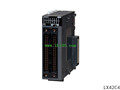
Product model: LX40C6
Name: I/O Module
Brand: MITSUBISHI
Sort: User's Manual
File language: English
Download link: MITSUBISHI LX40C6 User's Manual
Input points: 8 points.
Rated input voltage: AC100 ~ 120V.
Common way: 8 point / public end.
Input / output occupied points: 16 points (I/O distribution: 16 points).
External wiring connection: 18 point terminal.
The input and output module is also called control module, which can output signal when there is control requirement,
Or provide a switch signal to the controlled device,
At the same time, the feedback signal of the equipment can be received to report to the host computer,
Is an important part of the fire alarm linkage system,
The input and output modules in the market can provide a pair of passive normally open / normally closed contacts,
For controlling the controlled equipment, the module of the part can be set by the parameters,
Set to active output, corresponding to the two input and output modules, multiple input and output modules, and so on LX40C6 User's Manual LX40C6 User's Manual LX40C6 Output points: 64 points.
Output form: source type.
Rated output voltage: DC12 ~ 24V.
Max load current: 0.1A/1 point.
Protection function: have.
Common way: 32 point / public end.
Input / output occupied points: 64 points (I/O distribution: output 64 points) LX40C6 User's Manual.
External wiring connection: 40 pin connector two.
The switch input and output module is a device which can collect the input / output of the switch signal,
Digital I/O modules are often called.
The switch signal is collected to the computer or the computer to send the relevant instructions through the RS-485 bus to control the switch of the switch,
Can also be carried out through the RS-485 bus communication,
Remote control switch.
Communication protocol is a standard Modbus protocol or custom protocol. Open collector output.
Axis of control: 2.
Maximum output pulse: pulse/s 200k.
Location data: 600 data / axis.
Max link distance: 2m.
With the parameter setting, the synchronization control can be easily realized. Do not need to write complex procedures.
Start / stop with synchronous control of the shaft.
Synchronous control of the axis and the positioning of the axis can coexist.
Through the clutch, the movement of the main shaft can be transferred to the output shaft.
Simple implementation of synchronization control.
Cam control is more simple
Cam data can easily create a variety of patterns.
Can be simple to achieve the gear, shaft, transmission, cam and other mechanical mechanisms to replace the software synchronization control.
It is not subject to thhe limitation of the concept of the electronic cam control so far, and can use the cam with high degree of freedom LX40C6 Manual.
The stroke, speed, acceleration and beat can be confirmed on the graph, and the setting is carried out at the same timee LX40C6 Manual.
Can also be through the cam data thumbnail display, easy to confirm the cam data has been created.
Can import and export the cam data in CSV format.
Last one:
MITSUBISHI L26CPU-PBT Design, Maintenance and Inspection User's Manual
next one: MITSUBISHI LX42C4 User's Manual
next one: MITSUBISHI LX42C4 User's Manual
Related products
MITSUBISHI
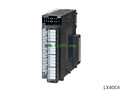
DC input module
LX42C4-CM
Enter points: 64 points.
Rated input vol
MITSUBISHI
DC input module
LX41C4-CM
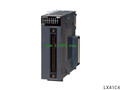
Input points: 32 points.
Rated input vol
MITSUBISHI
DC input module
LX40C6-CM
Input points: 16 points.
Rated input vol