LK Automation Limited
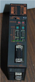
Ethernet Interface Module A1SJ71QE71N-B2 Hardware User's Manual MITSUBISHI A1SJ71QE71N-B2 Manual
Product model: A1SJ71QE71N-B2
Name: Ethernet Interface Module
Brand: MITSUBISHI
Sort: Hardware User's Manual
File language: English
Download link: MITSUBISHI A1SJ71QE71N-B2 User's Manual
Storage capacity: 64MB.
Applicable models: A985 (-V) /A975/A970/A960GOT (-B). Input type: DC input, positive common end.
Input points: 16 points.
Enter the response time: 0.2ms below, below 1.5ms, 5ms below, 10ms the following.
Rated input voltage / current: DC24V/7mA.
Output form: transistor output, leakage type A1SJ71QE71N-B2 User's Manual.
Output points: 16 points.
OFF leakage current: 0.1mA.
Output protection function: No A1SJ71QE71N-B2
Rated load voltage / current: DC24V/0.5A.
External connection: 1 line /1 line type.
According to the external connection mode and the external equipment input and output specifications,
Choose from a rich product lineup.
Finger protection through the upper part of the terminal,
The human body will not be exposed to live parts,
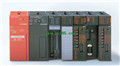
Therefore, the terminal station type remote I/O module can be directly mounted to the machine tool A1SJ71QE71N-B2 User's Manual. 8 slots.
Power supply unit.
QnA series unit installation.
High speed access.
CE logo fit.
I/O points is an important indicator of PLC.
Reasonable selection of I/O points can not only satisfy the control requirements of the system,
And the total investment of the system is the lowest A1SJ71QE71N-B2 User's Manual.
The input and output points and types of PLC should be determined according to the analog quantity and switch quantity of the controlled object,
Generally an input / output element to take up an input / output point.
Taking into account the future adjustment and expansion,
In general should be estimated on the total number of points plus the amount of spare 20%~30% MITSUBISHI A1SJ71QE71N-B2 Manual MITSUBISHI A1SJ71QE71N-B2 Manual.
When the programmer input programinto the user program memory,
Then CPU according to the function of the system (the system program memory to explain the compiler),
Translate the user program into PLC internally recognized by the user to compile the program.
Relay output interface circuit of PLC
Working process: when the internal circuit output digital signal 1,
There is a current flowing through, the relay coil has a current, and then the normally open contact is closed,
Provide load current and voltage MITSUBISHI A1SJ71QE71N-B2 Mannual A1SJ71QE71N-B2 Hardware.
When the internal circuit outputs a digital signal 0, there is no current flowing through it,
The relay coil does not have a current, and the normally open contact is broken off,
A current or voltage that is discoonnected from the load A1SJ71QE71N-B2 User's Manual.
It is through the output interface circuit to the internal digital circuit into a signal to make the load action or not action.
Applicable models: A985 (-V) /A975/A970/A960GOT (-B). Input type: DC input, positive common end.
Input points: 16 points.
Enter the response time: 0.2ms below, below 1.5ms, 5ms below, 10ms the following.
Rated input voltage / current: DC24V/7mA.
Output form: transistor output, leakage type A1SJ71QE71N-B2 User's Manual.
Output points: 16 points.
OFF leakage current: 0.1mA.
Output protection function: No A1SJ71QE71N-B2
Rated load voltage / current: DC24V/0.5A.
External connection: 1 line /1 line type.
According to the external connection mode and the external equipment input and output specifications,
Choose from a rich product lineup.
Finger protection through the upper part of the terminal,
The human body will not be exposed to live parts,
Therefore, the terminal station type remote I/O module can be directly mounted to the machine tool A1SJ71QE71N-B2 User's Manual. 8 slots.
Power supply unit.
QnA series unit installation.
High speed access.
CE logo fit.
I/O points is an important indicator of PLC.
Reasonable selection of I/O points can not only satisfy the control requirements of the system,
And the total investment of the system is the lowest A1SJ71QE71N-B2 User's Manual.
The input and output points and types of PLC should be determined according to the analog quantity and switch quantity of the controlled object,
Generally an input / output element to take up an input / output point.
Taking into account the future adjustment and expansion,
In general should be estimated on the total number of points plus the amount of spare 20%~30% MITSUBISHI A1SJ71QE71N-B2 Manual MITSUBISHI A1SJ71QE71N-B2 Manual.
When the programmer input programinto the user program memory,
Then CPU according to the function of the system (the system program memory to explain the compiler),
Translate the user program into PLC internally recognized by the user to compile the program.
Relay output interface circuit of PLC
Working process: when the internal circuit output digital signal 1,
There is a current flowing through, the relay coil has a current, and then the normally open contact is closed,
Provide load current and voltage MITSUBISHI A1SJ71QE71N-B2 Mannual A1SJ71QE71N-B2 Hardware.
When the internal circuit outputs a digital signal 0, there is no current flowing through it,
The relay coil does not have a current, and the normally open contact is broken off,
A current or voltage that is discoonnected from the load A1SJ71QE71N-B2 User's Manual.
It is through the output interface circuit to the internal digital circuit into a signal to make the load action or not action.
Last one:
MITSUBISHI AJ71QE71N-B2 Hardware User's Manual
next one: MITSUBISHI A1SD51S Hardware User's Manual
next one: MITSUBISHI A1SD51S Hardware User's Manual
Related products
MITSUBISHI
Serial communication module
A1SJ71QC24N-R2
RS-232 2 channel.
Transfer speed: 2 chan
MITSUBISHI
Ethernet module
AJ71QE71N-B2

10BASE2.
For Q mode.
Control layer /MELS
MITSUBISHI
Ethernet module
A1SJ71E71N-B2
10BASE2.
PLC is introduced y the relay