 LK Automation Limited
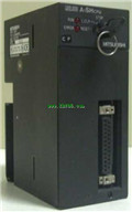
A2NCPU User's Manual MITSUBISHI A2NCPU Manual
Product model: A2NCPU
Name: PLC
Brand: MITSUBISHI
Sort: User's Manual
File language: English
Download link: MITSUBISHI A2NCPU User's Manual
3C-2V/5C-2V coaxial cable.
Single bus.
Remote I/O network (remote control station).
How to choose MITSUBISHI PLC.
MITSUBISHI PLC options include the choice of MITSUBISHI PLC models, capacity, I/O module, power, etc..
MITSUBISHI PLC distribution I/O points and design MITSUBISHI PLC peripheral hardware circuit
Draw the I/O point of the PLC and the input / output device connection diagram or the corresponding table,
This part also can be carried out in second steps MITSUBISHI A2NCPU Manual A2NCPU
Design PLC peripheral hardware circuit.
Draw the electrical wiring diagram of the other parts of the system,
Including the main circuit and the control circuit does not enter the PLC, etc..
The electrical schematic diagram of the system composed of I/O PLC connection diagram and PLC peripheral electrical circuit diagram MITSUBISHI A2NCPU Manual .
So far the system''s hardware electrical circuit has been determined. The use of A1STA32 can significantly reduce the wiring time I/O 32 type of connector assembly,
Neither welding, without thread stripping,
It only needs to cut a wire and insert the wire into the terminal hole of the A1STA32,
A1STA32 in the blade will cut wire insulation surface,
To make contact and hold a good conductor MITSUBISHI A2NCPU Manual . Cable length: 6 meters
Extending cable to connect CPU main substrate and extended substrate,
According to the model can provide different cable length,
If you need to connect the AnN type expansion substrate is required,
Selection of A1SC05NB (A1SC07NB) cable. Input type: DC input, positive public end / negative public end.
Input points: 32 points.
Enter the response time: 1.5ms the following.
Rated input voltage / current: DC24V/5mA.
External connection: 1 wire.
Fast connector type.
Simple wiring through quick connector.
Can be installed along the 6 direction.
MITSUBISHI PLC program simulation debugging
The basic idea of program simulation debugging is,
In order to facilitate the form of simulation to generate the actual state of the scene,
Create the necessary environmental conditions for the operation of the program.
Depending on the way the field signals are generated,
The simulation debugging has two forms of hardware simulation and software simulation. Input points: 32 points.
Input voltage and current: 3/7mA DC12/24V.
Input response time: 10ms.
16 point /1 a public side.
Output points: 24 points.
Output voltage: AC100 ~ 240V.
OFF leakage current: 3mA.
Output response time: 0.5Hz+1ms.
Output type: bidirectional thyristor output.
36 point terminal station.
With short circuit protection.
With the surge absorber.
Control solenoid valve required I/O points by the action principle of the solenoid valve can be known,
A single coil solenoid valve with PLC control to 2 input and 1 output,
A double coil solenoid valve requires 3 inputs and 2 outputs,
A button needs an input; a light sensitive switch needs 4 or 2 inputs,
A signal lamp needs 1 output, band switch,
Several bands are required for several inputs,
In general, a variety of position switches are required to take up 2 input points.
MITSUBISHI PLC is the main product in the production of MITSUBISHI motor in Dalian.
It uses a kind of programmable memory for its internal storage procedures,
Execute logic operation, sequence control, timing, counting and arithmetic operations, user oriented instruction,
And through digital or analog input / output control of various types of machinery or production process.
The number of I/O thyristor DC motor control required tube DC motor speed control system is the main form of DC speed regulation,
The thyristor rectifier unit is used to supply power to the DC motor.
PLC control of the DC drive system, the input of the PLC in addition to the main signal outside the signal,
We need to consider the switching signal, the fault signal transmission devicce, brake signal and fan fault signal A2NCPU User's Manual.
The output of the PLC mainly consider the speed command signal positive 1~3 level, 1~3 level, allowing reverse switching signal and brake open signal etc..
In general, a reversible DC drivee system controlled by PLC is approximately 12 input points and 8 output points,
An irreversible DC drive system requires 9 inputs and 6 output points A2NCPU User's Manual.
Related products
MITSUBISHI
General purpose CPU
Q20UDHCPU
Specification model: Q20UDHCPU.
Input /
MITSUBISHI
CPU component
A1SHCPU
I/O control method: refresh mode or dire
MITSUBISHI
Programmable logic controller CPU
R04CPU

Operation control mode: stored procedure
MITSUBISHI
Programmable logic controller CPU
R16CPU
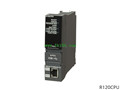
Operation control mode: stored procedure
Related download