 LK Automation Limited
A1NCPU Manual MITSUBISHI A1NCPU Dedicated Instructions Programming Manual
Product model: A1NCPU
Name: PLC
Brand: MITSUBISHI
Sort: Dedicated Instructions Programming Manual
File language: English
Download link: MITSUBISHI A1NCPU Programming Manual
Enter points: 64 points.
Input voltage: DC7V above.
Input response time: 16ms.
16 pin connector.
Output points: 64 points.
Output response time: 16ms.
Output type: transistor output.
32 pin connector.
Dynamic input and output.
Control solenoid valve required I/O points by the action principle of the solenoid valve can be known,
A single coil solenoid valve with PLC control to 2 input and 1 output,
A double coil solenoid valve requires 3 inputs and 2 outputs,
A button needs an input; a light sensitive switch needs 4 or 2 inputs,
A signal lamp needs 1 output, band switch,
Several bands are required for several inputs,
In general, a variety of position switches are required to take up 2 input points MITSUBISHI A1NCPU Programming Manual MITSUBISHI A1NCPU Programming Manual A1NCPU
MITSUBISHI PLC is the main product in the production of MITSUBISHI motor in Dalian.
It uses a kind of programmable memory for its internal storage procedures,
Execute logic operation, sequence control, timing, counting and arithmetic operations, user oriented instruction,
And through digital or analog input / output control of various types of machinery or production process.
The number of I/O thyristor DC motor control required tube DC motor speed control system is the main form of DC speed regulation,
The thyristor rectifier unit is used to supply power to the DC motor MITSUBISHI A1NCPU Programming Manual.
PLC control of the DC drive system, the input of the PLC in addition to the main signal outside the signal,
We need to consider the switching signal, the fault signal transmission device, brake signal and fan fault signal.
The output of the PLC mainly consider the speed command signal positive 1~3 level, 1~3 level, allowing reverse switching signal and brake open signal etc..
In general, a reversible DC drive system controlled by PLC is approximately 12 input points and 8 output points,
An irreversible DC drive system requires 9 inputs and 6 output points. 5 slots.
Can be installed in the power supply unit for AnS series units installed QnAS/.
The popularization and application of PLC programming has been developed rapidly in our country,
It has been widely used in all kinds of mechanical equipment and production process of electrical control devices,
All walks of life have emerged a large number of application of PLC transformation of the results of the equipment.
Understand the working principle of PLC, have the ability to design, debug and maintain the PLC control system,
Has become the basic requirements of modern industry for electrical technicians and engineering students.
PLC user program is designed according to the control system of the process control requirements,
PLC programming language through the preparation of specifications, in accordance with the actual needs of the use of the function to design A1NCPU Manual .
As long as the user caan master some kind of standard programming language,
To be able to use PLC in the control system,
To achieve a variety of automatic control functions A1NCPU Manual .
Last one:
MITSUBISHI A2NCPUR21 Dedicated Instructions Programming Manual
next one: MITSUBISHI A1NCPUP21 Dedicated Instructions Programming Manual
next one: MITSUBISHI A1NCPUP21 Dedicated Instructions Programming Manual
Related products
MITSUBISHI
CPU unit
A3ACPU
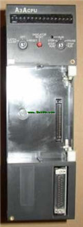
Input and output points: 2048 points.
In
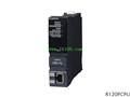
MITSUBISHI
General purpose CPU
Q10UDHCPU
Input / output points: 4096 points.
Num
MITSUBISHI
Moving CPU unit
A73CPU
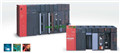
Multi axis positioning controller.
Progr
Related download