 LK Automation Limited
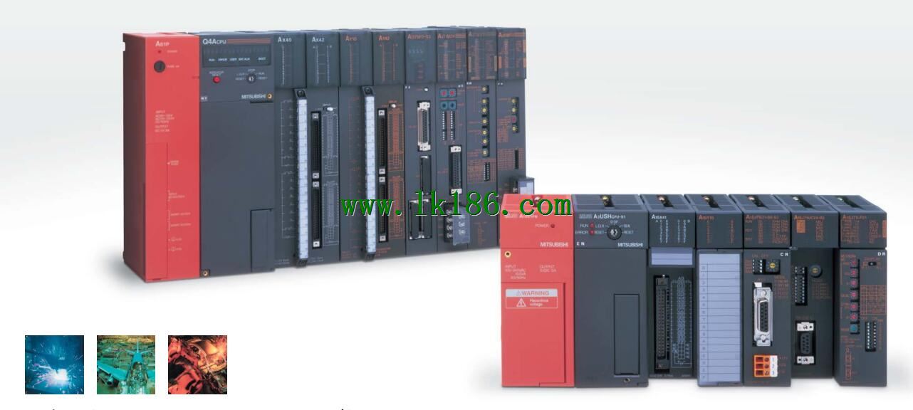
A68VB MITSUBISHI A68VB Extended bottom plate
Brand:
MITSUBISHI
Name: Extended bottom plate
Model: A68VB
A3VTS with additional floor.
Switch volume control is designed to,
According to the current input combination of the switch quantity and the history of the input sequence,
So that PLC generates the corresponding switching output,
In order to make the system work in a certain order.
So, sometimes also known as the order control.
And sequential control is divided into manual, semi-automatic or automatic.
And the control principle is decentralized, centralized and hybrid control three.
Each scanning process. Focus on the input signal sampling. Focus on the output signal to refresh.
Input refresh process. When the input port is closed,
Program in the implementation phase, the input end of a new state, the new state can not be read.
Only when the program is scanned, the new state is read.
A scan cycle is divided into the input sample, the program execution, the output refresh.
The contents of the component image register are changed with the change of the execution of the program.
The length of the scan cycle is determined by the three.
CPU the speed of executing instructions.
Time of instruction.
Instruction count.
Due to the adoption of centralized sampling.
Centralized output mode.
There exist input / output hysteresis phenomena, i.e., the input / output response delay.
System program memory for storing system program,
Including management procedures, monitoring procedures, as well as the user program to do the compiler to compile the process of interpretation.
Read only memory. Manufacturers use, content can not be changed, power does not disappear.
...More relevant models >>>>
Name: Extended bottom plate
Model: A68VB
A3VTS with additional floor.
Switch volume control is designed to,
According to the current input combination of the switch quantity and the history of the input sequence,
So that PLC generates the corresponding switching output,
In order to make the system work in a certain order.
So, sometimes also known as the order control.
And sequential control is divided into manual, semi-automatic or automatic.
And the control principle is decentralized, centralized and hybrid control three.
Each scanning process. Focus on the input signal sampling. Focus on the output signal to refresh.
Input refresh process. When the input port is closed,
Program in the implementation phase, the input end of a new state, the new state can not be read.
Only when the program is scanned, the new state is read.
A scan cycle is divided into the input sample, the program execution, the output refresh.
The contents of the component image register are changed with the change of the execution of the program.
The length of the scan cycle is determined by the three.
CPU the speed of executing instructions.
Time of instruction.
Instruction count.
Due to the adoption of centralized sampling.
Centralized output mode.
There exist input / output hysteresis phenomena, i.e., the input / output response delay.
System program memory for storing system program,
Including management procedures, monitoring procedures, as well as the user program to do the compiler to compile the process of interpretation.
Read only memory. Manufacturers use, content can not be changed, power does not disappear.
8 slots.
Power supply unit.
QnA series unit installation.
High speed access.
CE logo fit.
I/O points is an important indicator of PLC.
Reasonable selection of I/O points can not only satisfy the control requirements of the system,
And the total investment of the system is the lowest.
The input and output points and types of PLC should be determined according to the analog quantity and switch quantity of the controlled object,
Generally an input / output element to take up an input / output point MITSUBISHI A68VB A68VB
Taking into account the future adjustment and expansion,
In general should be estimated on the total number of points plus the amount of spare 20%~30%.
When the programmer input programinto the user program memory,
Then CPU according to the function of the system (the system program memory to explain the compiler),
Translate the user program into PLC internally recognized by the user to compile the program MITSUBISHI A68VB.
Relay output interface circuit of PLC
Working process: when the internal circuit output digital signal 1,
There is a current flowing through, the relay coil has a current, and then the normally open contact is closed,
Provide load current and voltage MITSUBISHI A68VB.
When the internal circuit outputs a digital signal 0, there is no current flowing through it,
The relay coil does not have a current, and the normally open contact is broken off,
A current or voltage that is disconnected from the load MITSUBISHI Extended bottom plate.
It is through the output interface circuit to the internal digital circuit into a signal to make the load action or not action MITSUBISHI Extended bottom plate. RS-232:1, RS-422/485:1.
Transmission speed: 0.3 ~ 19.2kpbs.
Computer connection function.
A3VCPU special.
Printer / peripheral device connection, BASIC language function.
How to choose MITSUBISHI PLC.
MITSUBISHI PLC options include the choice of MITSUBISHI PLC models, capacity, I/O module, power, etc MITSUBISHI Extended bottom plate. .
MITSUBISHI PLC distribution I/O points and design MITSUBISHI PLC peripheral hardware circuit
Draw the I/O point of the PLC and the input / output device connection diagram or the corresponding table,
This part also can be carried out in second steps.
Design PLC peripheral hardware circuit A68VB.
Draw the electrical wiring diagram of the other parts of the system,
Including the main circuit and the control circuit does not enter the PLC, etc..
The electrical schematic diagram of the system compoosed of I/O PLC connection diagram and PLC peripheral electrical circuit diagram MITSUBISHI A68VB.
So far the system''s hardware electrical circuit has been determined.
...More relevant models >>>>