 LK Automation Limited
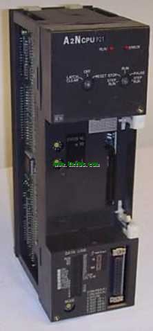
A2NCPUP21 MITSUBISHI A2NCPUP21 Input / output data points: 512 points
Brand:
MITSUBISHI
Name: CPU unit
Model: A2NCPUP21
Input and output points: 512 points.
Input / output data points: 512 points.
Program capacity: 14K.
Basic command processing speed (LD command) s:1.0.
Optical data communication line.
User program storage capacity: it is a measure of how much the user application can store the number of indicators.
Usually in words or K words as units. 16 bit binary number is a word,
Every 1024 words are 1K words. PLC to store instructions and data in words.
General logical operation instructions each account for 1 words. Timer / counter,
Shift instruction accounted for 2 words. Data operation instructions for 2~4.
Integral type: the PLC components are installed together or a few pieces of printed circuit board,
And together with the power supply installed in the casing to form a single overall called the host or the basic unit, small, ultra small PLC using this structure.
Modular: PLC is the basic components of a separate module.
Medium and large PLC used this way. Easy maintenance.
...More relevant models >>>>
Name: CPU unit
Model: A2NCPUP21
Input and output points: 512 points.
Input / output data points: 512 points.
Program capacity: 14K.
Basic command processing speed (LD command) s:1.0.
Optical data communication line.
User program storage capacity: it is a measure of how much the user application can store the number of indicators.
Usually in words or K words as units. 16 bit binary number is a word,
Every 1024 words are 1K words. PLC to store instructions and data in words.
General logical operation instructions each account for 1 words. Timer / counter,
Shift instruction accounted for 2 words. Data operation instructions for 2~4.
Integral type: the PLC components are installed together or a few pieces of printed circuit board,
And together with the power supply installed in the casing to form a single overall called the host or the basic unit, small, ultra small PLC using this structure.
Modular: PLC is the basic components of a separate module.
Medium and large PLC used this way. Easy maintenance.
GI fiber optic cable.
Dual loop for Q mode.
Remote I/O network (remote control station).
How to choose MITSUBISHI PLC.
MITSUBISHI PLC options include the choice of MITSUBISHI PLC models, capacity, I/O module, power, etc..
MITSUBISHI PLC distribution I/O points and design MITSUBISHI PLC peripheral hardware circuit
Draw the I/O point of the PLC and the input / output device connection diagram or the corresponding table,
This part also can be carried out in second steps MITSUBISHI A2NCPUP21 A2NCPUP21
Design PLC peripheral hardware circuit.
Draw the electrical wiring diagram of the other parts of the system,
Including the main circuit and the control circuit does not enter the PLC, etc..
The electrical schematic diagram of the system composed of I/O PLC connection diagram and PLC peripheral electrical circuit diagram MITSUBISHI A2NCPUP21.
So far the system''s hardware electrical circuit has been determined. Input voltage range: AC100 ~ 120V/AC200 ~ 240V.
Output voltage: DC5/12V.
Output current: 2.3A/1.5A.
I/O points is an important indicator of PLC.
Reasonable selection of I/O points can not only satisfy the control requirements of the system,
And the total investment of the system is the lowest MITSUBISHI A2NCPUP21.
The input and output points and types of PLC should be determined according to the analog quantity and switch quantity of the controlled object,
Generally an input / output element to take up an input / output point MITSUBISHI CPU unit.
Taking into account the future adjustment and expansion,
In general should be estimated on the total number of points plus the amount of spare 20%~30% MITSUBISHI CPU unit.
The following describes the centralized control system I/O points of the estimate.
Relay output interface circuit of PLC
Working process: when the internal circuit output digital signal 1,
There is a current flowing through, the relay coil has a current, and then the normally open contact is closed,
Provide load current and voltage MITSUBISSHI CPU unit A2NCPUP21.
When the internal circuit outputs a digital signal 0, there is no current flowing through it,
The relay coil does not have a current, and the normally open contact is broken off,
A current or voltage that is discoonnected from the load MITSUBISHI A2NCPUP21.
It is through the output interface circuit to the internal digital circuit into a signal to make the load action or not action.
...More relevant models >>>>
Related download