 LK Automation Limited
A1SJ71UC24-R4-S2 Data bits: 8 MITSUBISHI A1SJ71UC24-R4-S2
Brand:
MITSUBISHI
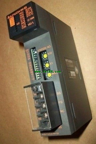
Name: MODBUS interface module
Model: A1SJ71UC24-R4-S2
Data format: RTU.
Data bits: 8.
A1SJ71UC24-R2-S2 and A1SJ71UC24-R4-S2 allow the Ans series PLC to be connected to the MODBUS network,
As the network from the station, and in accordance with the instructions of the main station of the CPU Ans user storage area for data reading / writing.
In addition to supporting the MODBUS protocol, these components also support the standard dedicated communication protocol for A1SJ71UC24 components.
This feature makes the main station of the data acquisition and control with more flexibility.
Support MODBUS slave station protocol.
Supports 1 to 21 function code.
Two transmission modes: RTU or ASCII.
...More relevant models >>>>
Name: MODBUS interface module
Model: A1SJ71UC24-R4-S2
Data format: RTU.
Data bits: 8.
A1SJ71UC24-R2-S2 and A1SJ71UC24-R4-S2 allow the Ans series PLC to be connected to the MODBUS network,
As the network from the station, and in accordance with the instructions of the main station of the CPU Ans user storage area for data reading / writing.
In addition to supporting the MODBUS protocol, these components also support the standard dedicated communication protocol for A1SJ71UC24 components.
This feature makes the main station of the data acquisition and control with more flexibility.
Support MODBUS slave station protocol.
Supports 1 to 21 function code.
Two transmission modes: RTU or ASCII.
8 slots; requires 1 AnS series PLC power modules;
Used to install large AnS series PLC module.
Base plate of AnS series PLC.
QA1S series PLC 8 slot main substrate.
AnS series of modules can be installed. 10BASE5.
Q mode.
MITSUBISHI PLC is the main product in the production of MITSUBISHI motor in Dalian MITSUBISHI A1SJ71UC24-R4-S2.
It uses a kind of programmable memory for its internal storage procedures,
Execute logic operation, sequence control, timing, counting and arithmetic operations, user oriented instruction,
And through digital or analog input / output control of various types of machinery or production process A1SJ71UC24-R4-S2
When the programmer input programinto the user program memory,
Then CPU according to the function of the system (the system program memory to explain the compiler),
Translate the user program into PLC internally recognized by the user to compile the program MITSUBISHI A1SJ71UC24-R4-S2. 3C-2V/5C-2V coaxial dual ring remote I/O network (remote I/O station).
Q mode.
When the programmer input programinto the user program memory,
Then CPU according to the function of the system (the system program memory to explain the compiler),
Translate the user program into PLC internally recognized by the user to compile the program MITSUBISHI A1SJ71UC24-R4-S2.
Input status and input information input from the input interface,
CPU will be stored in the working data memory or in the input image register.
And then combine the data and the program with CPU MITSUBISHI MODBUS interface module.
The result is stored in the output image register or the working data memory,
And then output to the output interface, control the external drive MITSUBISHI MODBUS interface module.
Semiconductor circuit with memory function.
System program memory and user memory.
System program memory for storing system program,
Including management procedures, monitoring procedures, as well as the user program to do the compiler to compile the process of interpretation MITSUBISHI MODBUS interface module.
Read only memory. Manufacturers use, content can not be changed, power does not disappear.
User memory: user program storage area and work data storage area.
Composed of random access memory (RAM). User use.
Power cut off. Commonly used efficient lithium battery as a backup power supply, life is generally 3~5 years. SI/QSI/H-PCF/ wide H-PCF optical cable dual layer remote I/O network (remote I/O station)
Switch volume control is designed to,
According to the current input combination of the switch quantity and the history of the input sequence,
So that PLC generates the corresponding switching output,
In order to make the system work in a certain order.
So, sometimes also known as the order control.
And sequential control is divided into manual, semi-automatic or automatic.
And the control principle is decentralized, centralized and hybrid control three.
The length of time required to execute the instruction, the length of the user''s program, the type of instruction, and the speed of the CPU execution are very significant,
Generally, a scanning process, the fault diagnosis time,
Communication time, input sampling and output refresh time is less,
The execution time is accounted for the vast majority of.
The response time of PLC is the interval between the time of the change of the external output signal of the PLC and the timme of the change of the external output signal which is controlled by it,
Lag time, this is the time constant of the input circuit,
The time constant of the output circuit, the arrangement of the user statement and the usse of the instruction,
The cycle scan mode of PLC and the way of PLC to refresh the I/O and so on MITSUBISHI A1SJ71UC24-R4-S2 A1SJ71UC24-R4-S2.
This phenomenon is called the I/O delay time effect.
...More relevant models >>>>
Related download