 LK Automation Limited
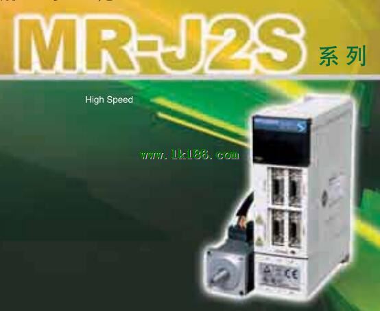
MITSUBISHI MR-J2S-200B4 MR-J2S-200B4
- Brand: MITSUBISHI(Mitsubishi)
- Country: JAPAN
- Name: SSCNET interface servo amplifier
- Model: MR-J2S-200B4
- Price: U.S.$ 3047.46
MITSUBISHI MR-J2S-200B4
1 axis servo amplifier.
MITSUBISHI general AC servo amplifier MELSERVO-J4 series.
Rated output: 11.0kw.
Interface: SSCNET III /H.
Power supply: three phase AC400V.
0.6kW and 1kW above the servo amplifier.
Servo amplifier supporting SSCNET III /H.
Complete synchronization system capable of using high speed serial optical communication MITSUBISHI MR-J2S-200B4.
Can be combined with the servo system controller to maximize the performance of the servo system MR-J2S-200B4
Improve mechanical properties by high performance motor.
By improving the resolution and processing speed of the encoder,
The rotating servo motor has higher precision and better performance of rotation MITSUBISHI MR-J2S-200B4.
Only open a key type of adjustment function, can be carried out including mechanical resonance filter, high end seismic control II, low pass filter servo gain adjustment .
Easily start advanced seismic function, it can maximize the mechanical properties.
It can automatically adjust the required response settings automatically. 3C-2V/5C-2V coaxial cable.
Single bus.
PC inter network (management station / station) / remote I/O network (remote control station) MITSUBISHI MR-J2S-200B4.
How to choose MITSUBISHI PLC.
MITSUBISHI PLC options include the choice of MITSUBISHI PLC models, capacity, I/O module, power, etc..
MITSUBISHI PLC distribution I/O points and design MITSUBISHI PLC peripheral hardware circuit
Draw the I/O point of the PLC and the input / output device connection diagram or the corresponding table,
This part also can be carried out in second steps.
Design PLC peripheral hardware circuit.
Draw the electrical wiring diagram of the other parts of the system,
Including the main circuit and the control circuit does not enter the PLC, etc..
The electrical schematic diagram of the system composed of I/O PLC connection diagram and PLC peripheral electrical circuit diagram.
So far the system''s hardware electrical circuit has been determined. Max input / output points: 48 points.
Supply voltage: 100 - 240VAC.
Input points: 24 points.
Output points: 24 points.
Output type: silicon controlled.
Power consumption: 50VA.
Weight (kg):0.85.
Size (WxHxD) mm:182x90x87.
Since the FX2n series have the following features: the maximum range of inclusive of the standard features, program execution faster, the full complement of communication function, suitable for different countries in the world, and the power to meet a large number of special function modules of individual needs,
It can provide maximum flexibility and control capability for your factory automation applications.
Control 16~256 point.
Built in 8K capacity of the RAM memory, the maximum can be extended to 16K.
CPU arithmetic processing speed of 0.08 S/ basic instructions.
On the right side of the FX2N series can be connected to the input and output expansion modules and special function modules.
The basic unit is built in the 2 axis independent maximum 20kHz positioning function (transistor output type).
Quick disconnect the terminal block, which adopts excellent maintainability to quickly disconnect the terminal blocks, even if the cable is then replaced by the cable.
Developed a range of special function modules to meet the needds of different - analog I/O, high speed counter MR-J2S-200B4.
Positioning control to achieve the 16 axis, the pulse train output or for the J and K type thermocouple or Pt sensor developed the temperature module.
A total of 8 special function mmoddules can be configured for each FX2n main unit MR-J2S-200B4.
Note recording function, Component annotation can be recorded in the program register.
Online program
MR-J2S-200B4 Operation manual/Instructions/Model selection sample download link: /searchDownload.html?Search=MR-J2S-200B4&select=5
...more relevant model market price >>>>
Related products
MITSUBISHI
Universal interface servo amplifier
MR-J2S-37KA
MITSUBISHI general purpose AC servo ampl
MITSUBISHI
Suitable for linear servo motor drive
MR-J3-200B4-RJ004
MITSUBISHI motor universal AC servo ampl
MITSUBISHI
Universal interface servo amplifier
MR-J2S-11KA4

MITSUBISHI general purpose AC servo ampl
MITSUBISHI
Universal interface servo amplifier
MR-J2S-45KA4

MITSUBISHI general purpose AC servo ampl