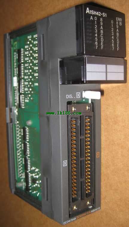
MITSUBISHI A1SH42-S1 A1SH42-S1
- Brand: MITSUBISHI(Mitsubishi)
- Country: JAPAN
- Name: Input / output module
- Model: A1SH42-S1
- Price: 0 >
MITSUBISHI A1SH42-S1
Cable length: 10m.
For connection between FXCPU (MINI-DIN8 pin connector) and GOT.
Connection between FXCPU communication function extension board (MINI-DIN8 pin connector) and GOT.
Applicable models: GT10, GT21. Max input / output points: 14 points.
Power supply voltage: DC24V.
Input points: 8 points MITSUBISHI A1SH42-S1.
Output points: 6 points.
Output type: relay.
Power consumption (W): 19.
Weight (kg):0.3.
Size (WxHxD) mm:60x90x75 A1SH42-S1
Positioning and pulse output functions: a PLC cell can output 2 point 100KHz pulses at the same time.
PLC is equipped with 7 special positioning instructions,
Including zero return, absolute or relative address expression and special pulse output control MITSUBISHI A1SH42-S1.
Host has 10 points (6I/4O), 14 points (8I/6O), 20 points (12I/8O), 30 points (16I/14O) of 4 types .
This type of PLC is mainly used in all of the digital input, digital output control point of the device.
Can be directly connected to the 220V city power, built-in 8K step EEPROM memory, no battery, easy to maintain.
The series transistor output (MT) of the PLC, can be output 2 100KHz pulse, direct drive servo or stepper motor MITSUBISHI A1SH42-S1.
The series PLC can not be brought with the expansion module, but can be installed by the BD board to extend a small amount of I/O.
The series 1N through the installation of BD series PLC board, can achieve RS232, RS485, RS422 communication. 2 slots.
No need to install power.
For QnA/A series.
Switch volume control is designed to,
According to the current input combination of the switch quantity and the history of the input sequence,
So that PLC generates the corresponding switching output,
In order to make the system work in a certain order.
So, sometimes also known as the order control.
And sequential control is divided into manual, semi-automatic or automatic.
And the control principle is decentralized, centralized and hybrid control three.
Each scanning process. Focus on the input signal sampling. Focus on the output signal to refresh.
Input refresh process. When the input port is closed,
Program in the implementation phase, the input end of a new state, the new state can not be read.
Only when the program is scanned, the new state is read.
A scan cycle is divided into the input sample, the program execution, the output refresh.
The contents of the component image register are changed with the change of the execution of the program.
The length of the scan cycle is determined by the three.
CPU the speed of executing instructions.
Time of instruction.
Instruction count.
Due to the adoption of centralized sampling.
Cenntralized outpput mode A1SH42-S1.
There exist input / output hysteresis phenomena, i.e., the input / output response delay.
System program memory for storing system program,
Including management procedures, monitoring procedures, as well as the user program tto do the compiler to compile the process of interpretation A1SH42-S1.
Read only memory. Manufacturers use, content can not be changed, power does not disappear.
A1SH42-S1 Operation manual/Instructions/Model selection sample download link: /searchDownload.html?Search=A1SH42-S1&select=5
...more relevant model market price >>>>
Related products
MITSUBISHI
Input / output module
A1SH42P-S1

Enter 32 points.
5mA DC24V.
Response tim
MITSUBISHI
Display module
AD22-S1

Can connect the transmitter units 2 unit
MITSUBISHI
Type DC input module
QX82-S1

Input points: 64 points.
Input voltage a
MITSUBISHI
CPU component
A1SHCPU

I/O control method: refresh mode or dire

