 LK Automation Limited
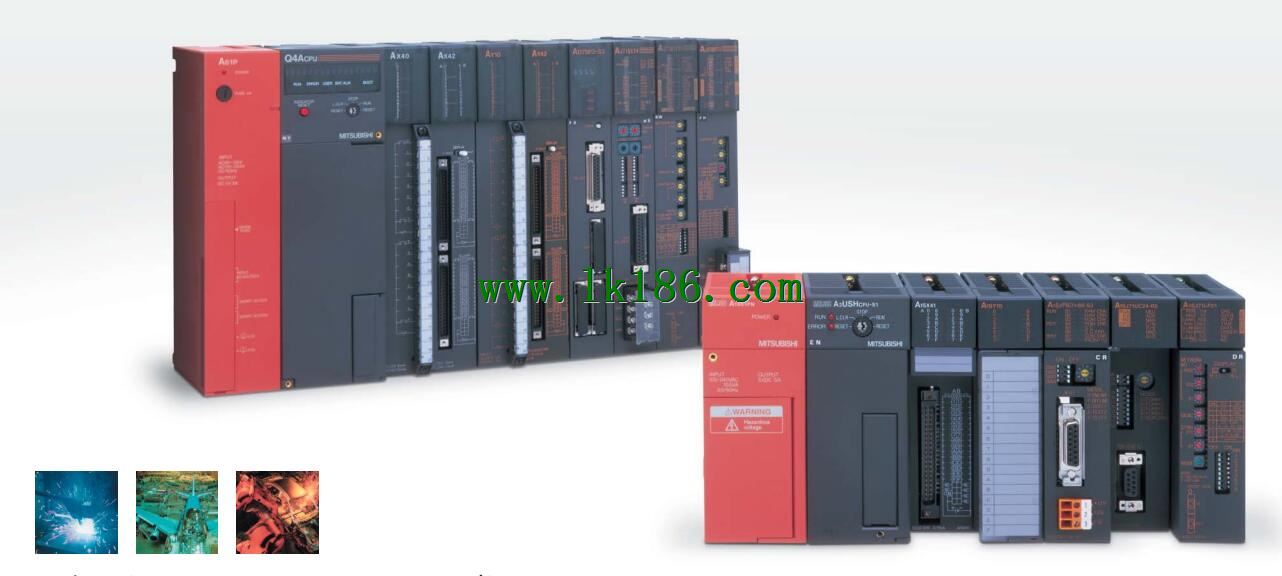
ME-NET interface unit
Structured text language is a programming language that describes a program with a structured description of the text.
It is a programming language similar to a high level language. In large and medium
Structured text is often used to describe the relationship between the various variables in the control system based on the PLC system AJ71C21-S1.
Mainly used for other programming languages more difficult to achieve the user program.
Functional block diagram language is a kind of PLC programming language, which is similar to digital logic circuit AJ71C21-S1.
The function module is used to represent the function of the module,
Different function modules have different functions.
Functional module figure programming language features: functional block diagram programming language is characterized by a functional module for the unit,
Analysis and understanding of the control scheme is simple and easy: function module is to use graphical form of expression,
Intuitive, for a digital logic circuit based on the design of the staff is very easy to master the programming;
Control system with complex scale and complex control logic,
Because the function module diagram can clearly express the function relation, the programming debugging time is greatly reduced AJ71C21-S1 MITSUBISHI AJ71C21-S1. Cable length: 15 meters.
For QCPU and GOT (need A9GT-QCNB) connection.
For the connection between GOT and GOT MITSUBISHI AJ71C21-S1.
RS-232:1 channel, RS-422:1 channel.
BASIC program mode (A3MCPU corresponding): BASIC console interface to use.
Sequential program mode (program controller CPU correspondence): non sequential computer connection interface and use.
How to choose MITSUBISHI PLC MITSUBISHI AJ71C21-S1.
MITSUBISHI PLC options include the choice of MITSUBISHI PLC models, capacity, I/O module, power, etc..
MITSUBISHI PLC distribution I/O points and design MITSUBISHI PLC peripheral hardware circuit
Draw the I/O point of the PLC and the input / output device connection diagram or the corresponding table,
This part also can be carried out in second steps.
Design PLC peripheral hardware circuit.
Draw the electrical wiring diagram of the other parts of the system,
Including the main circuit and the control circuit does not enter the PLC, etc AJ71C21-S1..
The electrical schematic diagram of the system composed of I/O PLC connection diagram and PLC peripheral electrical circuit diagram.
So far the system''s hardware electrical circuit has been determined.