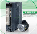
MITSUBISHI MR-J3-40B-RJ080W PDF catalog MR-J3-40B-RJ080W datasheet PDF datasheet
Product model: MR-J3-40B-RJ080W
Name: For direct drive servo motor drive
Brand: MITSUBISHI
Sort: PDF datasheet
File language: English
Download link: MITSUBISHI MR-J3-40B-RJ080W PDF datasheet
Drive: MR-H_ACN series CC-LINK features.
Rated output: 2.0KW.
The test system is composed of two parts, namely, the servo driver, the motor system and the host computer.
The host computer sends the speed command signal to the servo driver,
Servo drives start to run in accordance with the instructions MR-J3-40B-RJ080W PDF datasheet.
In the course of operation, the running data of the servo system is collected by the host computer and the data acquisition circuit,
And carries on the preservation, the analysis and the display to the data MR-J3-40B-RJ080W Because the motor is not loaded in this test system,
So compared with the previous two kinds of testing systems, the system has a relatively small volume,
And the measurement and control circuit of the system is relatively simple,
But it also makes the system can not simulate the actual operation of the servo drive MR-J3-40B-RJ080W PDF datasheet.
Usually, such testing system is only used to test the rotational speed and angular displacement of the tested system under no-load condition,
And can not carry on the comprehensive and accurate test to the servo drive. Type: MR-C type.
Symbol 10A for motor models: HC-PQ23 MR-J3-40B-RJ080W PDF datasheet.
Power supply voltage: single phase AC220V.
Drive: servo drive in the development of the premise of the frequency conversion technology,
Current loop in the drive,
Speed loop and position loop (frequency converter without the ring) have carried out a more precise control than the general frequency control technology and algorithm,
In function is also a lot stronger than the traditional servo,
The main point can be precise position control.
The control speed and position are controlled by the pulse sequence transmitted by the upper controller,
The internal algorithm of the driver and the faster and more accurate calculation and better performance of electronic devices to make it more superior to the inverter. Drive: MR-H_ACN series SSC-NET compatible AC servo.
Rated output: 0.1KW.
The servo controller can easily transfer the operation module and the field bus module through the automation interface,
At the same time using different fieldbus modules to achieve different control modes (RS485, RS232, optical fiber, InterBus, ProfiBus),
And the control mode of genneral inverter is single MR-J3-40B-RJ080W PDF catalog.
The servo controller is directly connected with a rotary transformer or an encoder, which forms a closed loop of speed and displacement control.
The general inverter can only form an open loop ccontrol system MR-J3-40B-RJ080W PDF catalog.
Servo controller of the control parameters (such as steady-state accuracy and dynamic performance) is better than the general inverter.
Related products
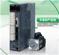
MITSUBISHI
For direct drive servo motor drive
MR-J3-40B-RJ080W

MITSUBISHI motor universal AC servo ampl
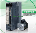
MITSUBISHI
For direct drive servo motor drive
MR-J3-11KB-RJ080W

MITSUBISHI motor universal AC servo ampl
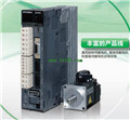
MITSUBISHI
For direct drive servo motor drive
MR-J3-700B-RJ080W

MITSUBISHI motor universal AC servo ampl
MITSUBISHI
For direct drive servo motor drive
MR-J3-60B-RJ080W

MITSUBISHI motor universal AC servo ampl
