 LK Automation Limited
MITSUBISHI AC30R2-9SS PDF catalog AC30R2-9SS datasheet PDF datasheet
Product model: AC30R2-9SS
Name: RS-232C cable
Brand: MITSUBISHI
Sort: PDF datasheet
File language: English
Download link: MITSUBISHI AC30R2-9SS PDF datasheet
Number of channels: 4 channels.
Sensing method and temperature range: PT100.
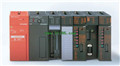
A1S64TC series component is a kind of temperature controller combined with ANS series CPU.
Components with temperature measurement input and built-in PID algorithm control output, can be used in a variety of temperature control occasions AC30R2-9SS PDF datasheet.
Each component controls up to 4 loops at most.
Thermocouple input or PT100 3 wire temperature sensor input AC30R2-9SS
Control output switching signal for the output of the transistor.
BW is a signal with broken line detection function. Fiber optic cable / twisted pair cable.
Single bus.
Remote I/O station.
According to the control requirements of the system, using the appropriate design method to design MITSUBISHI PLC program AC30R2-9SS PDF datasheet.
Procedures to meet the requirements of system control as the main line,
Write one by one to achieve the control function or the sub task of the program,
Gradually improve the functions specified by the system.
MITSUBISHI PLC initialization procedure. After MITSUBISHI PLC on power, the general need to do some of the initial operation,
In order to start making necessary preparations, to avoid the wrong operation of the system AC30R2-9SS PDF datasheet.
The main contents of the initialization program are: to some data area, counter and so on,
Data needed to restore some of the data area,
Set or reset some relays,
For some initial state display, etc.. Screw, 2 piece type terminal
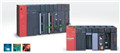
Thermocouple Input module.
Number of channels: 4 channels.
Number of stations: 1 stops.
Station type: remote equipment station.
MITSUBISHI PLC online debugging.
On-line debugging is the process that will through the simulation debugging to further carry on the on-line unification to adjust.
On-line debugging process should be step by step,
From MITSUBISHI PLC only connected to the input device, and then connect the output device, and then connect to the actual load and so on and so on step by step.
If you do not meet the requirements, the hardware and procedures for adjustment.
Usually only need to modify the part of the program can be.
MITSUBISHI PLC hardware implementation
Hardware implementation is mainly for the control cabinet and other hardware design and field construction.
Design control cabinet and the operating table and other parts of the electricaal wiring diagram and wiring diagram AC30R2-9SS PDF catalog.
Electrical interconnection diagram of each part of the design system.
According to the construction drawings of the site wiring, and carry out a detailed inspection.
Because the program deesign and hardware implementation can be carried out at the same time,
So the design cycle of the MITSUBISHI PLC control system can be greatly reduced AC30R2-9SS PDF catalog.
Sensing method and temperature range: PT100.
A1S64TC series component is a kind of temperature controller combined with ANS series CPU.
Components with temperature measurement input and built-in PID algorithm control output, can be used in a variety of temperature control occasions AC30R2-9SS PDF datasheet.
Each component controls up to 4 loops at most.
Thermocouple input or PT100 3 wire temperature sensor input AC30R2-9SS
Control output switching signal for the output of the transistor.
BW is a signal with broken line detection function. Fiber optic cable / twisted pair cable.
Single bus.
Remote I/O station.
According to the control requirements of the system, using the appropriate design method to design MITSUBISHI PLC program AC30R2-9SS PDF datasheet.
Procedures to meet the requirements of system control as the main line,
Write one by one to achieve the control function or the sub task of the program,
Gradually improve the functions specified by the system.
MITSUBISHI PLC initialization procedure. After MITSUBISHI PLC on power, the general need to do some of the initial operation,
In order to start making necessary preparations, to avoid the wrong operation of the system AC30R2-9SS PDF datasheet.
The main contents of the initialization program are: to some data area, counter and so on,
Data needed to restore some of the data area,
Set or reset some relays,
For some initial state display, etc.. Screw, 2 piece type terminal
Thermocouple Input module.
Number of channels: 4 channels.
Number of stations: 1 stops.
Station type: remote equipment station.
MITSUBISHI PLC online debugging.
On-line debugging is the process that will through the simulation debugging to further carry on the on-line unification to adjust.
On-line debugging process should be step by step,
From MITSUBISHI PLC only connected to the input device, and then connect the output device, and then connect to the actual load and so on and so on step by step.
If you do not meet the requirements, the hardware and procedures for adjustment.
Usually only need to modify the part of the program can be.
MITSUBISHI PLC hardware implementation
Hardware implementation is mainly for the control cabinet and other hardware design and field construction.
Design control cabinet and the operating table and other parts of the electricaal wiring diagram and wiring diagram AC30R2-9SS PDF catalog.
Electrical interconnection diagram of each part of the design system.
According to the construction drawings of the site wiring, and carry out a detailed inspection.
Because the program deesign and hardware implementation can be carried out at the same time,
So the design cycle of the MITSUBISHI PLC control system can be greatly reduced AC30R2-9SS PDF catalog.
Related products
MITSUBISHI
RS-422 cable
AC30R4-25P

Cale length: 3 meters.
For QnA/A/FX FX
MITSUBISHI
Cable
AC30R4
Cale connection and A7PU/A7HGP/A6GPP CP
MITSUBISHI
Programming unit cable
AC30R4-PUS
CPU-A8UPU/A8PUJ connection.
MITSUBISHI
RS-232C cable
AC30R2-9SS
Cale length: 3 meters.
Connection etwe
Related download