 LK Automation Limited
MITSUBISHI A1SY41 PDF datasheet A1SY41 datasheet PDF catalog
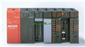
Product model: A1SY41
Name: Transistor leakage type output module
Brand: MITSUBISHI
Sort: PDF datasheet
File language: English
Download link: MITSUBISHI A1SY41 PDF datasheet
RS-232 1 channel.
RS-422/485 1 channel.
Transfer speed: 0.3-19.2kbps.
Input status and input information input from the input interface,
CPU will be stored in the working data memory or in the input image register.
And then combine the data and the program with CPU.
The result is stored in the output image register or the working data memory,
And then output to the output interface, control the external drive A1SY41 PDF datasheet A1SY41
Semiconductor circuit with memory function.
System program memory and user memory.
System program memory for storing system program,
Including management procedures, monitoring procedures, as well as the user program to do the compiler to compile the process of interpretation.
Read only memory A1SY41 PDF datasheet. Manufacturers use, content can not be changed, power does not disappear. Write adapter for EPROM 28 pinScrew, 2 piece type terminal
Thermocouple Input module.
Number of channels: 4 channels.
Number of stations: 1 stops.
Station type: remote equipment station.
MITSUBISHI PLC online debugging.
On-line debugging is the process that will through the simulation debugging to further carry on the on-line unification to adjust A1SY41 PDF datasheet.
On-line debugging process should be step by step,
From MITSUBISHI PLC only connected to the input device, and then connect the output device, and then connect to the actual load and so on and so on step by step.
If you do not meet the requirements, the hardware and procedures for adjustment.
Usually only need to modify the part of the program can be.
MITSUBISHI PLC hardware implementation
Hardware implementation is mainly for the control cabinet and other hardware design and field construction.
Design control cabinet and the operating table and other parts of the electrical wiring diagram and wiring diagram.
Electrical interconnection diagram of each part of the design system.
According to the construction drawings of the site wiring, and carry out a detailed inspection.
Because the program design and hardware implementation can be carried out at the same time,
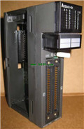
So the design cycle of the MITSUBISHI PLC control system can be greatly reduced. Input channel number: 4.
Output channel number: 2.
Occupy I/O points: 64.
A1S63ADA analog input / output combination components can be analog / digital / digital / analog conversion,
The input and output signals can be voltage or current,
Offset and gain can be set and stored.
The length of time required to execute the instruction, the length of the user''s program, the type of instruction, and the speed of the CPU execution are very significant,
Generally, a scanning process, the fault diagnosis time,
Communication time, input sampling and output refresh time is less,
The execution time is accounted for the vast majority of.
The response time of PLC is the interval between the time of the change of the external output signal of the PLC annd the time of the change of the external output signal which is controlled by it,
Lag time, this is the time constant of the input circuit,
The time constant of the output circuit, the arrangement of the user statement and the usse of the instruction,
The cycle scan mode of PLC and the way of PLC to refresh the I/O and so on A1SY41 PDF catalog A1SY41 PDF catalog.
This phenomenon is called the I/O delay time effect.
RS-422/485 1 channel.
Transfer speed: 0.3-19.2kbps.
Input status and input information input from the input interface,
CPU will be stored in the working data memory or in the input image register.
And then combine the data and the program with CPU.
The result is stored in the output image register or the working data memory,
And then output to the output interface, control the external drive A1SY41 PDF datasheet A1SY41
Semiconductor circuit with memory function.
System program memory and user memory.
System program memory for storing system program,
Including management procedures, monitoring procedures, as well as the user program to do the compiler to compile the process of interpretation.
Read only memory A1SY41 PDF datasheet. Manufacturers use, content can not be changed, power does not disappear. Write adapter for EPROM 28 pinScrew, 2 piece type terminal
Thermocouple Input module.
Number of channels: 4 channels.
Number of stations: 1 stops.
Station type: remote equipment station.
MITSUBISHI PLC online debugging.
On-line debugging is the process that will through the simulation debugging to further carry on the on-line unification to adjust A1SY41 PDF datasheet.
On-line debugging process should be step by step,
From MITSUBISHI PLC only connected to the input device, and then connect the output device, and then connect to the actual load and so on and so on step by step.
If you do not meet the requirements, the hardware and procedures for adjustment.
Usually only need to modify the part of the program can be.
MITSUBISHI PLC hardware implementation
Hardware implementation is mainly for the control cabinet and other hardware design and field construction.
Design control cabinet and the operating table and other parts of the electrical wiring diagram and wiring diagram.
Electrical interconnection diagram of each part of the design system.
According to the construction drawings of the site wiring, and carry out a detailed inspection.
Because the program design and hardware implementation can be carried out at the same time,
So the design cycle of the MITSUBISHI PLC control system can be greatly reduced. Input channel number: 4.
Output channel number: 2.
Occupy I/O points: 64.
A1S63ADA analog input / output combination components can be analog / digital / digital / analog conversion,
The input and output signals can be voltage or current,
Offset and gain can be set and stored.
The length of time required to execute the instruction, the length of the user''s program, the type of instruction, and the speed of the CPU execution are very significant,
Generally, a scanning process, the fault diagnosis time,
Communication time, input sampling and output refresh time is less,
The execution time is accounted for the vast majority of.
The response time of PLC is the interval between the time of the change of the external output signal of the PLC annd the time of the change of the external output signal which is controlled by it,
Lag time, this is the time constant of the input circuit,
The time constant of the output circuit, the arrangement of the user statement and the usse of the instruction,
The cycle scan mode of PLC and the way of PLC to refresh the I/O and so on A1SY41 PDF catalog A1SY41 PDF catalog.
This phenomenon is called the I/O delay time effect.
Related products
MITSUBISHI
Extension cable
A1SC30B
Cale length: 3 meters
Extending cale t
MITSUBISHI
CPU substrate
A1S38B
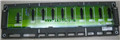
I/O slots: 8 slots.
Outline dimension: 4
MITSUBISHI
CPU base plate
A1S33B
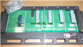
I/O slots: 3 slots.
Outline dimension: 2
Related download