 LK Automation Limited
MITSUBISHI A1S55B PDF catalog A1S55B datasheet PDF datasheet
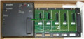
Product model: A1S55B
Name: Extended bottom plate
Brand: MITSUBISHI
Sort: PDF datasheet
File language: English
Download link: MITSUBISHI A1S55B PDF datasheet
Cable length: 30.6 meters.
Small CPU long distance connecting cable.
For QnAS/AnSCPU/ motion control and GOT connection.
For connection between A7GT-CNB and GOT.
Combination A8GT-EXCNB and A8GT-C_BS. Screw terminal table type.
High precision / high resolution / high speed 2 piece type terminal.
Voltage / current output module A1S55B PDF datasheet.
Number of channels: 2 channels.
Number of stations: 1 stops A1S55B
Station type: remote equipment station.
MITSUBISHI PLC hardware implementation
Hardware implementation is mainly for the control cabinet and other hardware design and field construction.
Design control cabinet and the operating table and other parts of the electrical wiring diagram and wiring diagram.
Electrical interconnection diagram of each part of the design system A1S55B PDF datasheet.
According to the construction drawings of the site wiring, and carry out a detailed inspection.
Because the program design and hardware implementation can be carried out at the same time,
So the design cycle of the MITSUBISHI PLC control system can be greatly reduced.
MITSUBISHI PLC online debugging.
On-line debugging is the process that will through the simulation debugging to further carry on the on-line unification to adjust A1S55B PDF datasheet.
On-line debugging process should be step by step,
From MITSUBISHI PLC only connected to the input device, and then connect the output device, and then connect to the actual load and so on and so on step by step.
If you do not meet the requirements, the hardware and procedures for adjustment.
Usually only need to modify the part of the program can be. 8 slots.
Power supply unit.
QnAS series unit installation.
High speed access.
CE logo fit.
I/O points is an important indicator of PLC.
Reasonable selection of I/O points can not only satisfy the control requirements of the system,
And the total investment of the system is the lowest.
The input and output points and types of PLC should be determined according to the analog quantity and switch quantity of the controlled object,
Generally an input / output element to take up an input / output point.
Taking into account the future adjustment and expansion,
In general should be estimated on the total number of points plus the amount of spare 20%~30%.
When the programmer input programinto the user program memory,
Then CPU according to the function of the system (the system program memory to explain the compiler),
Translate the user program into PLC internally recognized by the user to compile the program.
Relay output interface circuit of PLC
Working process: when the internal circuit output digital signal 1,
There is a current flowing through, the relay coil has a current, and then the normally open contact is closed,
Provide load curreent and voltage A1S55B PDF catalog.
When the internal circuit outputs a digital signal 0, there is no current flowing through it,
The relay coil does not have a current, and the normally open contact is broken off,
A current or voltage that is discoonnected from the load A1S55B PDF catalog.
It is through the output interface circuit to the internal digital circuit into a signal to make the load action or not action.
Related products
MITSUBISHI
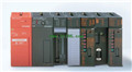
CPU unit
A1SJCPU
Program memory capacity: 8k.
Input / out
MITSUBISHI
Network module
A1SJ71LR21
3C-2V/5C-2V coaxial cale etween doule
MITSUBISHI
Melsecnet interface module
A1SJ71AP21GE
PLC station distance: 2Km.
Cale type: G