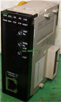
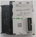
CompoBus/S Master Unit CJ1W-SRM21 datasheet PDF datasheet OMRON CJ1W-SRM21 PDF catalog
Product model: CJ1W-SRM21
Name: CompoBus/S Master Unit
Brand: OMRON
Sort: PDF datasheet
File language: English
Download link: OMRON CJ1W-SRM21 PDF datasheet
One Ethernet Option Board can be mounted in either option board slot 1 or 2.
Note: Cannot be used for the CP1L-L10.CPU Unit: CP1L-M CPU Units with 30 Points.
Specifications: CPU type, Memory capacity: 10K steps
High-speed counters: 100 kHz, 4 axes Pulse outputs:
100 kHz, 2 axes (Models with transistor outputs only);
Power supply, DC power supply; Output method, Relay output;
Inputs, 18; Output, 12 CJ1W-SRM21 PDF datasheet CJ1W-SRM21
Standards: UC1, N, L, CE.
High Performing Programmable Controller with Embedded Ethernet.
"CP1L-EM" and "CP1L-EL" has a standard-feature Ethernet port.
"CP1L-M" and "CP1L-L" has a standard-feature peripheral USB port.
Function blocks (FB) allow you to build up modular structure and,
programming of ladder diagrams CJ1W-SRM21 PDF datasheet . Name: Two-tier Screw Terminal Block.
Specifications: Outputs; 8 outputs; PNP.
"Easy" and "Flexible" system expansion,
with linked CC-Link and CompoNet.
Branching is easily made with CompoNet.
Wiring material cost can be reduced.
Bit-level I/O distribution reduces,
wiring in the system.
A wide variety of CompoNet Slave Units,
contribute to system size reduction CJ1W-SRM21 PDF datasheet .
Seven-segment Display on the Gateway Unit,
helps to detect errors on site.
The Participation Flags and Communications,
Error Flags can be checked at the Host,
Controller to detect the location and,
content of the error. I/O bits: 960 (Expan-sion Racks: 2) OMRON CJ1W-SRM21 PDF catalog.
Program capacity: 20K steps.
Data memory capacity: 64K words (DM: 32K words, EM: 32K words ×1 bank)Unit type: CS1 Special I/O Units OMRON CJ1W-SRM21 PDF catalog.
Product name: Isolated-type,
Resistance Thermocouple Input Units.
points Input: 4 inputs.
Signal range selection:
Set separately for each input.
I/O type: Pt100, JPt100, Pt50, Ni508.4.
Conversion speed (resolution):
20 ms/4 inputs, 10 ms/2 inputs.
Externa connection: Removable erminal block OMRON CJ1W-SRM21 PDF catalog.
No. of unit numbers allocated: 1.
Current consumption: 5V, 0.12A; 26V, 0.07A.
Standards: UC1, N, CE.
Provides the functionality of isolators,
power supplies, signal converters,
and other devices.
The Analog Input Unit converts analog,
input signals such as 1 to 5 V or 4 to 20mA,
into digital values, and takes the values,
scaled in industrial units, and transfers,
it to the CPU Unit as the process value.
Because of this, no ladder program is required,
at the CPU Unit for scaling.
The Analog Output Unit converts analog output set,
values from the CPU Unit to analog output signals,
such as 4 to 20 mA or 1 to 5 V, and outputs them.
The built-in functions, such as measurement value,
alarms, rate-of-change calculations, and square roots,
have enabled major savings in cost and space comppared,
with previous systems CJ1W-SRM21 datasheet.
High-resolution Models and 8-point Input Models are,
also available.
By combining the Units, logging/monitoring.
systems can be constructed,
or the Units can be used together with LCBs/LCCUs,
to construct complete process control systems CJ1W-SRM21 PDF datasheet .
Parameters can be easily displayed and set in an,
easy-to-understand form without special tools.
Related products
OMRON
Position Control Units
CJ1W-NC213

Unit classification: CJ1 Special I/O Uni
OMRON
Ethernet Unit
CJ1W-ETN21

Unit type: CJ1 CPU Bus Unit.
Product Na
OMRON
Analog I/O Unit
CJ1W-AD081-V1

Unit type: CJ1 Special I/O Units.
Pro
OMRON
CJ1W-CIF21

CompoWay/F adapter for communications wi
