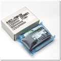
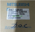
A9GT-BUS2S PDF catalog MITSUBISHI Bus connecting plate A9GT-BUS2S datasheet PDF datasheet
Product model: A9GT-BUS2S
Name: Bus connecting plate
Brand: MITSUBISHI
Sort: PDF datasheet
File language: English
Download link: MITSUBISHI A9GT-BUS2S PDF datasheet
3C-2V/5C-2V coaxial cable between the single bus PC network (control station / common station) / remote I/O network (remote master).
Q mode.
When the programmer input programinto the user program memory,
Then CPU according to the function of the system (the system program memory to explain the compiler),
Translate the user program into PLC internally recognized by the user to compile the program MITSUBISHI Bus connecting plate PDF datasheet A9GT-BUS2S
Input status and input information input from the input interface,
CPU will be stored in the working data memory or in the input image register.
And then combine the data and the program with CPU.
The result is stored in the output image register or the working data memory,
And then output to the output interface, control the external drive MITSUBISHI Bus connecting plate PDF datasheet.
Semiconductor circuit with memory function.
System program memory and user memory.
System program memory for storing system program,
Including management procedures, monitoring procedures, as well as the user program to do the compiler to compile the process of interpretation.
Read only memory. Manufacturers use, content can not be changed, power does not disappear MITSUBISHI Bus connecting plate PDF datasheet.
User memory: user program storage area and work data storage area.
Composed of random access memory (RAM). User use.
Power cut off. Commonly used efficient lithium battery as a backup power supply, life is generally 3~5 years A9GT-BUS2S PDF datasheet. A pack of 20.
Applicable models:
AJ65SBTC - - - type remote I/O module.
AJ65VBTCU - - - type remote I/O module A9GT-BUS2S PDF datasheet.
AJ65VBTCU- - type remote I/O module. Output type: transistor source / drain type.
Output points: 8 points.
Load voltage: DC5/12/24/48.
Load current: 2A.
Connection mode: terminal row.
Common public end points: 1.
Switching value, also known as logic, refers to only two values, 0 or 1, ON or OFF A9GT-BUS2S PDF datasheet.
It is the most common control, it is the advantage of PLC control,
Is also the most basic application of PLC.
Switch volume control is designed to,
According to the current input combination of the switch quantity andd the history of the input sequence,
So that PLC generates the corresponding switching output,
In order to make the system work in a certain order A9GT-BUS2S PDF catalog.
So, sometimes also known as the order control.
And seqquential control is divided into manual, semi-automatic or automatic MITSUBISHI Bus connecting plate PDF datasheet.
And the control principle is decentralized, centralized and hybrid control three.
Related products
MITSUBISHI
Printer interface unit
A9GT-50PRF

Parallel printer connection 1CH.
Appli
MITSUBISHI
Memory card
A9GT-FNB1M

Optional features of memory card A/FX c
MITSUBISHI
Bus connecting plate
A9GT-QBUSS

QCPU Q mode us connection.
1 joint.
A

