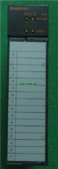
A62DA PDF catalog MITSUBISHI Analog output module A62DA datasheet PDF datasheet
Product model: A62DA
Name: Analog output module
Brand: MITSUBISHI
Sort: PDF datasheet
File language: English
Download link: MITSUBISHI A62DA PDF datasheet
Data communication line module (coaxial cable) Master / local station for A3VTS multiplex system.
MITSUBISHI PLC detection, fault diagnosis and display and other procedures.
These procedures are relatively independent, generally in the basic completion of the program design and then add.
MITSUBISHI PLC protection and chain procedures MITSUBISHI Analog output module PDF datasheet.
Protection and chain is an indispensable part of the program, must be carefully considered A62DA
It can avoid the control logic confusion caused by illegal operations. Series Name: A975GOT.
Size: 10 inches.
Resolution: 600 * 480.
Display equipment: high brightness TFT color display.
Display color: 16 color.
Power supply: DC24V.
Memory card: 1M.
Man machine interface is the interface between man and machine in the field of information exchange and function contact or influence,
Information exchange, functional contact or mutual influence, the hard contact and soft touch of a person and machine,
This interface includes not only the direct contact point line side,
It also includes the function of remote information transmission and control MITSUBISHI Analog output module PDF datasheet.
The man-machine interface is the central link in the man-machine system,
Mainly from the safety engineering branch of the safety ergonomics to study and put forward the basis for the solution,
And over the safety engineering equipment engineering, safety management engineering and safety systems engineering to study the specific solutions and measures to the safety of human computer science and technology MITSUBISHI Analog output module PDF datasheet A62DA PDF datasheet A62DA PDF datasheet.
It realizes the transformation between the internal form of information and the acceptable form of human being. Remote I/O controller, optical fiber GI.
How to choose MITSUBISHI PLC.
MITSUBISHI PLC options include the choice of MITSUBISHI PLC models, capacity, I/O module, power, etc A62DA PDF datasheet. .
MITSUBISHI PLC distribution I/O points and design MITSUBISHI PLC peripheral hardware circuit
Draw the I/O point of the PLC and the input / output device connection diagram or the corresponding table,
This part also can be carried out in second steps.
Design PLC peripheral hardware circuit.
DDraw the electrical wiring diagram of the other parts of the system,
Including the main circuit and the control circuit does not enter the PLC, etc A62DA PDF catalog. .
The electrical schematic diagram of the system compoosed of I/O PLC connection diagram and PLC peripheral electrical circuit diagram MITSUBISHI Analog output module PDF datasheet.
So far the system''s hardware electrical circuit has been determined.
Related products
MITSUBISHI
Extended bottom plate
A65B

5 slots.
To install the power supply.
Fo
MITSUBISHI
Optical media conversion
A6BSW-P-S3

Self service IN, OUT: SI optical cale
MITSUBISHI
Analog input module
A68ADN

8 channels.
Input: DC-10 10V, -20 20
MITSUBISHI
Analog input / output module
A1S66ADA

Input channel numer: 4.
Output channel
