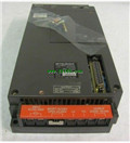
Programmable Logic Controller A0J2CPU-DC24 Common Instructions Programming Manual MITSUBISHI A0J2CPU-DC24 Manual
Product model: A0J2CPU-DC24
Name: Programmable Logic Controller
Brand: MITSUBISHI
Sort: Common Instructions Programming Manual
File language: English
Download link: MITSUBISHI A0J2CPU-DC24 Programming Manual
Fiber optic cable / twisted pair cable.
Single bus.
Remote I/O station.
According to the control requirements of the system, using the appropriate design method to design MITSUBISHI PLC program.
Procedures to meet the requirements of system control as the main line,
Write one by one to achieve the control function or the sub task of the program,
Gradually improve the functions specified by the system A0J2CPU-DC24 Programming Manual A0J2CPU-DC24
MITSUBISHI PLC initialization procedure. After MITSUBISHI PLC on power, the general need to do some of the initial operation,
In order to start making necessary preparations, to avoid the wrong operation of the system.
The main contents of the initialization program are: to some data area, counter and so on,
Data needed to restore some of the data area,
Set or reset some relays,
For some initial state display, etc A0J2CPU-DC24 Programming Manual . . Close to input / output: 8 DC input or keyboard: 64 DC input, 16 transistor output.
Applicable models: A95_GOT (-M3) /A956WGOT. Input type: DC input, positive common end.
Input points: 16 points.
Enter the response time: 0.2ms the following.
Rated input voltage / current: DC24V/5mA A0J2CPU-DC24 Programming Manual .
Output form: transistor output, leakage type.
Output points: 16 points.
OFF leakage current: 0.1mA.
Output protection function: No.
Rated load voltage / current: DC24V/0.5A.
External connection: 1 line /1 line type MITSUBISHI A0J2CPU-DC24 Manual.
According to the external connection mode and the external equipment input and output specifications,
Choose from a rich product lineup MITSUBISHI A0J2CPU-DC24 Manual.
Finger protection through the upper part of the terminal,
The human body will not be exposed to live parts,
Therefore, the terminal station type remote I/O module can be directly mounted to the machine tool. Input type: DC input, positive public end / negative public end.
Input points: 32 points MITSUBISHI A0J2CPU-DC24 Manual.
Enter the response time: 0.2ms the following.
Rated input voltage / current: DC24V/5mA.
External connection: 1 wire.
Fast connector type.
Simple wiring through quick connector.
Can be installed along the 6 direction.
MITSUBISHI PLC program simulation debuggging
The basic idea of program simulation debugging is,
In order to facilitate the form of simulation to generate the actual state of the scene,
Create the necessary environmental conditions for the operation of thee program A0J2CPU-DC24 Programming Manual A0J2CPU-DC24 Common Instructions.
Depending on the way the field signals are generated,
The simulation debugging has two forms of hardware simulation and software simulation.
Last one:
MITSUBISHI A3ACPUP21-S3 Common Instructions Programming Manual
next one: MITSUBISHI A0J2CPU-DC24-S2 Common Instructions Programming Manual
next one: MITSUBISHI A0J2CPU-DC24-S2 Common Instructions Programming Manual
Related products
MITSUBISHI
CPU unit
A0J2CPUP23

Input and output points: 480 points.
Pro
MITSUBISHI
CPU unit
A0J2CPUR23

Input and output points: 480 points.
Pro
MITSUBISHI
CPU unit
A0J2CPU

Input and output points: 480 points.
Pro
MITSUBISHI
CPU unit
A0J2CPU-DC24-S2

Input and output points: 480 points.
Pro
Related download
