 LK Automation Limited
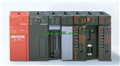
Positioning Module A1SD75P3-S3 Manual MITSUBISHI A1SD75P3-S3 User's Manual
Product model: A1SD75P3-S3
Name: Positioning Module
Brand: MITSUBISHI
Sort: User's Manual
File language: English
Download link: MITSUBISHI A1SD75P3-S3 User's Manual
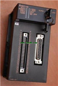
Input type: DC input, positive public end / negative public end.
Input points: 32 points.
Enter the response time: 0.2ms the following.
Rated input voltage / current: DC24V/5mA.
External connection: 1 wire.
Fast connector type.
Simple wiring through quick connector.
Can be installed along the 6 direction A1SD75P3-S3 Manual.
MITSUBISHI PLC program simulation debugging
The basic idea of program simulation debugging is,
In order to facilitate the form of simulation to generate the actual state of the scene,
Create the necessary environmental conditions for the operation of the program A1SD75P3-S3
Depending on the way the field signals are generated,
The simulation debugging has two forms of hardware simulation and software simulation A1SD75P3-S3 Manual. The A1SP60 pulse capture module is a 16 point DC24V input module,
Can be used as a general input module,
Can also be used as a pulse capture module,
Pulse capture function makes the input signal width in the sequence can be as short as 0.5ms,
Once there is a pulse signal input, the state is memory,
A1SP60 to ensure that the control process at least once again to control the state of the memory of the operation,
Input can be set to 4 blocks,
Each block can be set to a general function or pulse capture function A1SD75P3-S3 Manual. Twisted pair cable.
Single bus.
MELSECNET/B (Master / local station).
According to the control requirements of the system, using the appropriate design method to design MITSUBISHI PLC program MITSUBISHI A1SD75P3-S3 User's Manual.
Procedures to meet the requirements of system control as the main line,
Write one by one to achieve the control function or the sub task of the program,
Gradually improve the functions specified by the system MITSUBISHI A1SD75P3-S3 User's Manual.
MITSUBISHI PLC initialization procedure. After MITSUBISHI PLC on power, the general need to do some of the initial operation,
In order to start making necessary preparations, to avoid the wrong operation of the system MITSUBISHI A1SD75P3-S3 User's Manual.
The main contents of the initialization program are: to some data area, counter and so on,
Data needed to restore some of the data area,
Set or reset some relays,
For some initial state display, etc.. Type of input: DC leakage.
Input points: 32 points.
Input voltage: DC24.
Input current: 7mA.
Connection mode: terminal row.
Common common point: 32.
Functional block diagram language is a kind of PLC programming language, which is similar to digital logic circuit.
The function module is used to represent the function of the module,
Different function modules have different functions.
Functional module figure programming language features: functional block diagram programming language is characterized by a functional module for the unit,
Analysis and understanding of the control schemee is simple and easy: function module is to use graphical form of expression,
Intuitive, for a digital logic circuit based on the design of the staff is very easy to master the programming;
Control system with complex scale and coomplex control logic,
Because the function module diagram can clearly express the function relation, the programming debugging time is greatly reduced A1SD75P3-S3 Manual A1SD75P3-S3 .
Input points: 32 points.
Enter the response time: 0.2ms the following.
Rated input voltage / current: DC24V/5mA.
External connection: 1 wire.
Fast connector type.
Simple wiring through quick connector.
Can be installed along the 6 direction A1SD75P3-S3 Manual.
MITSUBISHI PLC program simulation debugging
The basic idea of program simulation debugging is,
In order to facilitate the form of simulation to generate the actual state of the scene,
Create the necessary environmental conditions for the operation of the program A1SD75P3-S3
Depending on the way the field signals are generated,
The simulation debugging has two forms of hardware simulation and software simulation A1SD75P3-S3 Manual. The A1SP60 pulse capture module is a 16 point DC24V input module,
Can be used as a general input module,
Can also be used as a pulse capture module,
Pulse capture function makes the input signal width in the sequence can be as short as 0.5ms,
Once there is a pulse signal input, the state is memory,
A1SP60 to ensure that the control process at least once again to control the state of the memory of the operation,
Input can be set to 4 blocks,
Each block can be set to a general function or pulse capture function A1SD75P3-S3 Manual. Twisted pair cable.
Single bus.
MELSECNET/B (Master / local station).
According to the control requirements of the system, using the appropriate design method to design MITSUBISHI PLC program MITSUBISHI A1SD75P3-S3 User's Manual.
Procedures to meet the requirements of system control as the main line,
Write one by one to achieve the control function or the sub task of the program,
Gradually improve the functions specified by the system MITSUBISHI A1SD75P3-S3 User's Manual.
MITSUBISHI PLC initialization procedure. After MITSUBISHI PLC on power, the general need to do some of the initial operation,
In order to start making necessary preparations, to avoid the wrong operation of the system MITSUBISHI A1SD75P3-S3 User's Manual.
The main contents of the initialization program are: to some data area, counter and so on,
Data needed to restore some of the data area,
Set or reset some relays,
For some initial state display, etc.. Type of input: DC leakage.
Input points: 32 points.
Input voltage: DC24.
Input current: 7mA.
Connection mode: terminal row.
Common common point: 32.
Functional block diagram language is a kind of PLC programming language, which is similar to digital logic circuit.
The function module is used to represent the function of the module,
Different function modules have different functions.
Functional module figure programming language features: functional block diagram programming language is characterized by a functional module for the unit,
Analysis and understanding of the control schemee is simple and easy: function module is to use graphical form of expression,
Intuitive, for a digital logic circuit based on the design of the staff is very easy to master the programming;
Control system with complex scale and coomplex control logic,
Because the function module diagram can clearly express the function relation, the programming debugging time is greatly reduced A1SD75P3-S3 Manual A1SD75P3-S3 .
Last one:
MITSUBISHI A1SD75P2-S3 User's Manual
next one: MITSUBISHI A1SD75P1-S3 Hardware User's Manual
next one: MITSUBISHI A1SD75P1-S3 Hardware User's Manual
Related products
MITSUBISHI
Pulse output positioning control module
A1SD71-S2
Axis of control: 2.
A1SD71-S2 is a linea

MITSUBISHI
Positioning control module
A1SD75M2
Axis of control: 2.
Interpolation functi