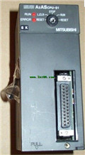
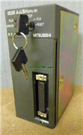
MITSUBISHI A2USHCPU-S1 Programming Manual PLC Dedicated Instructions Manual
Product model: A2USHCPU-S1
Name: PLC
Brand: MITSUBISHI
Sort: Dedicated Instructions Programming Manual
File language: English
Download link: MITSUBISHI A2USHCPU-S1 Programming Manual
Cable length: 0.45 meters
Extending cable to connect CPU main substrate and extended substrate,
According to the model can provide different cable length,
If you need to connect the AnN type expansion substrate is required,
Selection of A1SC05NB (A1SC07NB) cable. 10BASE-T.
For Q mode.
Control layer /MELSECNET/10 (H) is the middle layer of the whole network system,
Control network which is convenient and high speed processing data transmission between PLC, CNC and other control equipment A2USHCPU-S1 Manual A2USHCPU-S1
As MELSEC control network MELSECNET/10,
With its good real-time performance, simple network settings, no procedures of the network data sharing concept,
As well as the redundant circuit and so on, has obtained the very high market appraisal,
The number of devices to reach the highest in japan,
In the world is also one of the few A2USHCPU-S1 Manual .
And MELSECNET/H not only inherited the excellent characteristics of MELSECNET/10,
Also makes the network real-time better, more data capacity,
Further adapt to the needs of the market. QnA/ACPU bus connection.
2 joint.
Applicable models: A985 (-V) /975/970/960GOT. 3C-2V/5C-2V coaxial cable A2USHCPU-S1 Manual .
Single bus.
Remote I/O network (remote control station).
How to choose MITSUBISHI PLC.
MITSUBISHI PLC options include the choice of MITSUBISHI PLC models, capacity, I/O module, power, etc..
MITSUBISHI PLC distribution I/O points and design MITSUBISHI PLC peripheral hardware circuit
Draw the I/O point of the PLC and the input / output device connection diagram or the corresponding table,
This part also can be carried out in second steps MITSUBISHI PLC Manual MITSUBISHI PLC Manual .
Design PLC peripheral hardware circuit.
Draw the electrical wiring diagram of the other parts of the system,
Including the main circuit and the control circuit does not enter the PLC, etc..
The electrical schematic diagram of the system composed of I/O PLC connection diagram and PLC peripheral electrical circuit diagram MITSUBISHI PLC Manual .
So far the system''s hardware electrical circuit has been determined. RS-232 1 channel.
RS-422/485 1 channel.
Transfer speed: 2 channels.
A total of 115.2kbps.
Input status and input information input from the input interface,
CPU will be stored in the working data memory or in the input image register.
And then combine the data and the program with CPU.
The result is stored in the output image register or the working data memory,
And then output to the output interface, control the externnal drive A2USHCPU-S1 Programming Manual.
Semiconductor circuit with memory function.
System program memory and user memory.
System program memory for storing system program,
Including management procedures, monitoring procedures, as well as the user program tto do the compiler to compile the process of interpretation A2USHCPU-S1 Manual .
Read only memory. Manufacturers use, content can not be changed, power does not disappear.
Last one:
MITSUBISHI A2ASCPU-S1 Dedicated Instructions Programming Manual
next one: MITSUBISHI A2ASCPU-S60 Dedicated Instructions Programming Manual
next one: MITSUBISHI A2ASCPU-S60 Dedicated Instructions Programming Manual
Related products
MITSUBISHI
CPU unit
A2ASCPU-S1

I/O points: 512.
Processing speed: sec/
MITSUBISHI
CPU unit
A2SCPU-S1

Program memory capacity 14K.
Input and o
MITSUBISHI
CPU unit
A2USHCPU-S1

I/O points: 1024.
Processing speed: 0.09
MITSUBISHI
CPU unit
A1SCPU-S1

Program memory capacity: 8k.
Input / out
Related download
