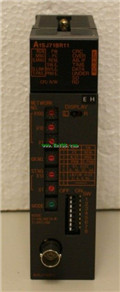
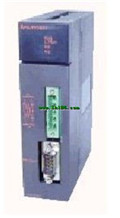
MITSUBISHI A1SJ72QLR25 Manual A1SJ72QLR25 Reference Manual
Product model: A1SJ72QLR25
Name: MELSECNET/10 Network System
Brand: MITSUBISHI
Sort: Reference Manual
File language: English
Download link: MITSUBISHI A1SJ72QLR25 Reference Manual
Cable length: 0.7 meters
Extending cable to connect CPU main substrate and extended substrate,
According to the model can provide different cable length,
If you need to connect the AnN type expansion substrate is required,
Selection of A1SC05NB (A1SC07NB) cable. RS-422 connection (QnA/A/FXCPU direct connection, computer connection, micro computer connection) A1SJ72QLR25 Reference Manual .
No clock function A1SJ72QLR25
Applicable models: A985 (-V) /975/970/960GOT. 10BASE-T.
Q mode.
MITSUBISHI PLC is the main product in the production of MITSUBISHI motor in Dalian.
It uses a kind of programmable memory for its internal storage procedures,
Execute logic operation, sequence control, timing, counting and arithmetic operations, user oriented instruction,
And through digital or analog input / output control of various types of machinery or production process A1SJ72QLR25 Reference Manual .
When the programmer input programinto the user program memory,
Then CPU according to the function of the system (the system program memory to explain the compiler),
Translate the user program into PLC internally recognized by the user to compile the program. SI/QSI/H-PCF/ wide range H-PCF fiber optic cable A1SJ72QLR25 Reference Manual .
Double loop.
PC inter network (management station / station) / remote I/O network (remote control station).
How to choose MITSUBISHI PLC.
MITSUBISHI PLC options include the choice of MITSUBISHI PLC models, capacity, I/O module, power, etc..
MITSUBISHI PLC distribution I/O points and design MITSUBISHI PLC peripheral hardware circuit
Draw the I/O point of the PLC and the input / output device connection diagram or the corresponding table,
This part also can be carried out in second steps.
Design PLC peripheral hardware circuit.
Draw the electrical wiring diagram of the other parts of the system,
Including the main circuit and the control circuit does not enter the PLC, etc..
The electrical schematic diagram of the system composed of I/O PLC connection diagram and PLC peripheral electrical circuit diagram.
So far the system''s hardware electrical circuit has been determined. Twisted pair cable.
Single bus.
Remote I/O station.
According to the control requirements of the system, using the appropriate design method to design MITSUBISHI PLC program.
Procedures to meet the requirements of system control as the main line,
Write one by one to achieve the control function or the sub task of the program,
Gradually improve the functions specified by the system.
MITSUBISHI PLC initialization procedure. After MITSUBISHI PLC on power, the general need to do some of the initial operation,
In order to start making necessary preparations, to avoid the wrong operation of the system A1SJ72QLR25 Manual .
The main contents of the initialization program arre: to some data area, counter and so on,
Data needed to restore some of the data area,
Set or reset some relays,
For some initial state display, etc A1SJ72QLR25 Manual . .
Related products
MITSUBISHI
Network module
A1SJ71BR11

3C-2V/5C-2V coaxial cale etween the si
MITSUBISHI
Computer communication module
A1SJ71UC24-R4

Interface: RS422/485
Transmission distan
MITSUBISHI
Coaxial cable module
AJ72QLR25

3C-2V/5C-2V coaxial cale.
Doule loop.

