 LK Automation Limited
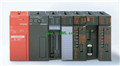
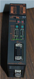
MITSUBISHI A1SJ71QC24N1-R2 Manual A1SJ71QC24N1-R2 Modem Function Additional Version User's Manual
Product model: A1SJ71QC24N1-R2
Name: Serial Communications Module
Brand: MITSUBISHI
Sort: Modem Function Additional Version User's Manual
File language: English
Download link: MITSUBISHI A1SJ71QC24N1-R2 User's Manual
Output type: transistor output, drain type.
Output points: 16 points.
OFF leakage current: 0.1mA.
Output protection function: No.
Rated load voltage / current: DC12V/DC24V/0.5A.
External connection: 2 wire.
Spring clip terminal.
Do not need to be tightened further or locked with screws, which can reduce the working hours of wiring A1SJ71QC24N1-R2 User's Manual.
Using 2 pieces of structure of the terminal units, maintenance can be maintained in the same line under the condition of the replacement module A1SJ71QC24N1-R2
When installing the module can choose to use the DIN guide rail or screw mounting.
Can be used for the 3 wire sensor input wiring. DC input points: 16 points.
Input voltage and current: 5mA, DC24V.
Response time: 10ms.
16 point /1 a public side A1SJ71QC24N1-R2 User's Manual.
Positive / negative sharing.
Output points: 16 points.
Output voltage and current: DC24V, 0.1A/1 point, 1.6A/1 common end.
Response time: 2ms.
16 point /1 a public side.
Output form: transistor output, leakage type.
40 pin connector.
Number of stations: 4 stops.
According to the control requirements of the system, using the appropriate design method to design MITSUBISHI PLC program A1SJ71QC24N1-R2 User's Manual.
Procedures to meet the requirements of system control as the main line,
Write one by one to achieve the control function or the sub task of the program,
Gradually improve the functions specified by the system.
MITSUBISHI PLC detection, fault diagnosis and display and other procedures.
These procedures are relatively independent, generally in the basic completion of the program design and then add.
Hardware simulation method is to use a number of hardware equipment to simulate the generation of the signal,
The signals are connected to the input end of the PLC system in a hard wired way, and the timeliness is strong.
Software simulation method is in the MITSUBISHI PLC in the preparation of a set of simulation program,
The simulation provides the field signal, which is simple and easy to operate, but it is not easy to guarantee the timeliness.
Simulation of the process of debugging, debugging method can be used to segment, and the monitoring function of programmer. Enter 32 points.
2/5mA DC12/24V.
Response time: 10ms.
32 point 1 public.
Output 32 points.
DC12/24V.
Leakage current: 0.1mA OFF.
Response time: 1ms.
32 point 1 public.
Protection function.
Surge.
40 pin connector.
Switching value, also known as logic, refers to only two values, 0 or 1, ON or OFF.
It is the most common control, it is the advantage of PLC control,
Is also the most basic application of PLC.
Switch volume control is designed to,
According to the current input combination of the switch quantity and the history of the input sequence,
So that PLC generates the corresponding switching output,
In order to make the system work in a certain order A1SJ71QC24N1-R2 Manual .
So, sometimes also known as the order control.
And seqquential control is divided into manual, semi-automatic or automatic A1SJ71QC24N1-R2 Manual .
And the control principle is decentralized, centralized and hybrid control three.
Output points: 16 points.
OFF leakage current: 0.1mA.
Output protection function: No.
Rated load voltage / current: DC12V/DC24V/0.5A.
External connection: 2 wire.
Spring clip terminal.
Do not need to be tightened further or locked with screws, which can reduce the working hours of wiring A1SJ71QC24N1-R2 User's Manual.
Using 2 pieces of structure of the terminal units, maintenance can be maintained in the same line under the condition of the replacement module A1SJ71QC24N1-R2
When installing the module can choose to use the DIN guide rail or screw mounting.
Can be used for the 3 wire sensor input wiring. DC input points: 16 points.
Input voltage and current: 5mA, DC24V.
Response time: 10ms.
16 point /1 a public side A1SJ71QC24N1-R2 User's Manual.
Positive / negative sharing.
Output points: 16 points.
Output voltage and current: DC24V, 0.1A/1 point, 1.6A/1 common end.
Response time: 2ms.
16 point /1 a public side.
Output form: transistor output, leakage type.
40 pin connector.
Number of stations: 4 stops.
According to the control requirements of the system, using the appropriate design method to design MITSUBISHI PLC program A1SJ71QC24N1-R2 User's Manual.
Procedures to meet the requirements of system control as the main line,
Write one by one to achieve the control function or the sub task of the program,
Gradually improve the functions specified by the system.
MITSUBISHI PLC detection, fault diagnosis and display and other procedures.
These procedures are relatively independent, generally in the basic completion of the program design and then add.
Hardware simulation method is to use a number of hardware equipment to simulate the generation of the signal,
The signals are connected to the input end of the PLC system in a hard wired way, and the timeliness is strong.
Software simulation method is in the MITSUBISHI PLC in the preparation of a set of simulation program,
The simulation provides the field signal, which is simple and easy to operate, but it is not easy to guarantee the timeliness.
Simulation of the process of debugging, debugging method can be used to segment, and the monitoring function of programmer. Enter 32 points.
2/5mA DC12/24V.
Response time: 10ms.
32 point 1 public.
Output 32 points.
DC12/24V.
Leakage current: 0.1mA OFF.
Response time: 1ms.
32 point 1 public.
Protection function.
Surge.
40 pin connector.
Switching value, also known as logic, refers to only two values, 0 or 1, ON or OFF.
It is the most common control, it is the advantage of PLC control,
Is also the most basic application of PLC.
Switch volume control is designed to,
According to the current input combination of the switch quantity and the history of the input sequence,
So that PLC generates the corresponding switching output,
In order to make the system work in a certain order A1SJ71QC24N1-R2 Manual .
So, sometimes also known as the order control.
And seqquential control is divided into manual, semi-automatic or automatic A1SJ71QC24N1-R2 Manual .
And the control principle is decentralized, centralized and hybrid control three.
Last one:
MITSUBISHI A1SJ71QC24-R2 Modem Function Additional Version User's Manual
next one: MITSUBISHI AJ71QC24N Modem Function Additional Version User's Manual
next one: MITSUBISHI AJ71QC24N Modem Function Additional Version User's Manual
Related products
MITSUBISHI
Ethernet module
A1SJ71QE71N-B2
10BASE2.
Q mode.
MITSUBISHI PLC is the m
MITSUBISHI
Serial communication module
A1SJ71QC24N-R2
RS-232 2 channel.
Transfer speed: 2 chan
MITSUBISHI
Network module
A1SJ71QE71N-B5T

Ethernet network module 10BASE-T / 10BAS
MITSUBISHI
Serial communication module
A1SJ71QC24

RS-232 1 channel.
RS-422/485 1 channel.