 LK Automation Limited
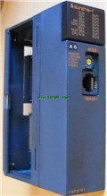
MITSUBISHI A1SD51S User's Manual Intelligent Communication Module Manual
Product model: A1SD51S
Name: Intelligent Communication Module
Brand: MITSUBISHI
Sort: User's Manual
File language: English
Download link: MITSUBISHI A1SD51S User's Manual
RS-232:1 channel, RS-422:1 channel.
BASIC program mode (A3MCPU corresponding): BASIC console interface to use.
Sequential program mode (program controller CPU correspondence): non sequential computer connection interface and use.
How to choose MITSUBISHI PLC.
MITSUBISHI PLC options include the choice of MITSUBISHI PLC models, capacity, I/O module, power, etc A1SD51S Manual. .
MITSUBISHI PLC distribution I/O points and design MITSUBISHI PLC peripheral hardware circuit
Draw the I/O point of the PLC and the input / output device connection diagram or the corresponding table,
This part also can be carried out in second steps A1SD51S
Design PLC peripheral hardware circuit.
Draw the electrical wiring diagram of the other parts of the system,
Including the main circuit and the control circuit does not enter the PLC, etc A1SD51S Manual. .
The electrical schematic diagram of the system composed of I/O PLC connection diagram and PLC peripheral electrical circuit diagram.
So far the system''s hardware electrical circuit has been determined. Output points: 16 points.
Voltage: DC24V/AC240V, 2A/1 point, 16A/ all points.
OFF leakage current: 0 A1SD51S Manual. 1mA.
Output type: relay output.
Response time: 12ms.
All points of independence.
38 point terminal station.
With the surge absorber.
The number of I/O thyristor DC motor control required tube DC motor speed control system is the main form of DC speed regulation,
The thyristor rectifier unit is used to supply power to the DC motor MITSUBISHI Intelligent Communication Module Manual.
PLC control of the DC drive system, the input of the PLC in addition to the main signal outside the signal,
We need to consider the switching signal, the fault signal transmission device, brake signal and fan fault signal MITSUBISHI Intelligent Communication Module Manual.
The output of the PLC mainly consider the speed command signal positive 1~3 level, 1~3 level, allowing reverse switching signal and brake open signal etc MITSUBISHI Intelligent Communication Module Manual. .
In general, a reversible DC drive system controlled by PLC is approximately 12 input points and 8 output points,
An irreversible DC drive system requires 9 inputs and 6 output points.
MITSUBISHI PLC is the main product in the production of MITSUBISHI motor in Dalian.
It uses a kind of programmable memory for its internal storage procedures,
Execute logic operation, sequence control, timing, counting and arithmetic operations, user oriented instruction,
And through digital or analog input / output control of various types of machinery or production process.
Control solenoid valve required I/O points by the action principle of the solenoid valve can be known,
A single coil solenoid valve with PLC control to 2 input and 1 output,
A double coil solenoid valve requires 3 inputs and 2 outputs,
A button needs an input; a light sensitive switch needs 4 or 2 inputs,
A signal lamp needs 1 output, band switch,
Several bands are required for several inputs,
In general, a variety of position switches are required to take up 2 input points A1SD51S Manual A1SD51S User's Manual.
Last one:
MITSUBISHI A1SJ71E71-B5 User's Manual
next one: MITSUBISHI AD51H-BASIC Command Programming Manual
next one: MITSUBISHI AD51H-BASIC Command Programming Manual
Related products

MITSUBISHI
Network module
A1SJ71E71N-T
10BASE-T
MITSUBISHI PLC is the main prod
MITSUBISHI
Melsecnet remote interface module
A1SJ72T25B
By MELSECNET/B I/O can e decentralized