 LK Automation Limited
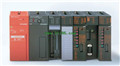
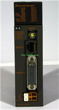
Ethernet Interface Module A1SJ71E71-B5 Manual MITSUBISHI A1SJ71E71-B5 User's Manual
Product model: A1SJ71E71-B5
Name: Ethernet Interface Module
Brand: MITSUBISHI
Sort: User's Manual
File language: English
Download link: MITSUBISHI A1SJ71E71-B5 User's Manual
Series Name: A956GOT.
Size: 6 inches.
Resolution: 320 * 240.
Display device: STN color display.
Display color: 8 color.
Power supply: DC24V.
Memory card: 1M.
The external model design model of creating the system function is mainly to consider the data structure, the overall structure and the process description of the software,
The interface design is usually only used as accessories, only on the user''s situation (including age, gender, mental status, education level, personality, ethnic background and etc A1SJ71E71-B5 Manual A1SJ71E71-B5 ) to understand, to design an effective user interface;
According to the user model of the future system of the end user (for short),
In the end, it is consistent with the system image (external characteristic) of the system after the system is realized,
Users can be satisfied with the system and be able to use it effectively;
When the user model is established, the information given by the system should be considered,
System mapping must accurately reflect the syntax and semantic information of the system A1SJ71E71-B5 Manual.
In short, only to understand the user, to understand the task in order to design a good man-machine interface A1SJ71E71-B5 Manual. G1-50/125 fiber optic cable.
Double loop.
PC inter network (management station / station) / remote I/O network (remote control station).
How to choose MITSUBISHI PLC.
MITSUBISHI PLC options include the choice of MITSUBISHI PLC models, capacity, I/O module, power, etc MITSUBISHI A1SJ71E71-B5 User's Manual. .
MITSUBISHI PLC distribution I/O points and design MITSUBISHI PLC peripheral hardware circuit
Draw the I/O point of the PLC and the input / output device connection diagram or the corresponding table,
This part also can be carried out in second steps MITSUBISHI A1SJ71E71-B5 User's Manual.
Design PLC peripheral hardware circuit.
Draw the electrical wiring diagram of the other parts of the system,
Including the main circuit and the control circuit does not enter the PLC, etc MITSUBISHI A1SJ71E71-B5 User's Manual. .
The electrical schematic diagram of the system composed of I/O PLC connection diagram and PLC peripheral electrical circuit diagram.
So far the system''s hardware electrical circuit has been determined. DC input points: 8 points.
Input voltage and current: 4/10mA DC12/24V.
Response time: 10ms.
8 point /1 a public side.
Positive pole sharing.
26 point terminal station.
Number of stations: 1 stops.
Type remote I/O unit (twisted pair data connection).
Equipment layer / field bus CC-Link device layer is the PLC and other control devices and sensors and drive devices connected to the field network,
Network for the lowest layer of the whole network system.
Using CC-Link field bus connection, the number of wiring is greatly reduced,
Improve the maintainability of the system.
And, not just the amount of data ON/OFF and other switches,
Can also be connected to the ID system, bar code reader, inverter, man-machine interface and other intelligent devices,
From the completion of a variety of data communication, the management of the terminal production information can be realized,
On the centralized management of the state of the machine movement,
Make maintenance work efficiency also greatly improved.
Q series PLC in the use of CC-Link function better,
And easier to use.
Mitsubishi Co PLC network inherited the traditional use of the MELSEC network,
And make it better in terms of performance, function, easy to use etc..
Provides a layer of three layers of clear network, to provide the most suitable network products for a variety of uses.
The information layer /Ethernet (Ethernet) information layer is the highest level of the network system,
Mainly in the PLC, the device controller and production management with PC transmission between production management information, quality management information and the operation of equipment, etc.,
Information layer using the most common Ethernet.
It is not only able to connect the PC system UNIX, windows system, etc.,
And can connect a variety of FA devices.
The Ethernet modulle has the function of Internet e-mail receiving and sending,
The user can send and receive the production information conveniently in any place of the world,
Build a remote monitoring management system A1SJ71E71-B5 .
At the same time, tthe use of the Internet FTP server functions and MELSEC protocol can be very easy to achieve the program upload / download and transfer of information A1SJ71E71-B5 Manual.
Related products
MITSUBISHI
Ethernet module
A1SJ71E71N3-T
10BASE-T.
The structured text programmin
MITSUBISHI
Ethernet module
A1SJ71E71N-B5
10BASE5.
PLC is introduced y the relay