 LK Automation Limited
MITSUBISHI A1SCPU Manual A1SCPU Common Instructions Programming Manual
Product model: A1SCPU
Name: Programmable Logic Controller
Brand: MITSUBISHI
Sort: Common Instructions Programming Manual
File language: English
Download link: MITSUBISHI A1SCPU Programming Manual
DC input points: 2 points.
Input voltage and current: 7mA, DC24V.
Input response time: 10ms.
2 point /1 a public side.
Positive / negative sharing.
Output points: 2 points.
Output voltage and current: DC24V/AC240V, 2A/1 point, 4A/1 common end.
Output response time: 2ms.
2 point /1 a public side.
Output form: relay A1SCPU Programming Manual .
16 point terminal station.
MITSUBISHI PLC protection and chain procedures A1SCPU
Protection and chain is an indispensable part of the program, must be carefully considered.
It can avoid the control logic confusion caused by illegal operations.
MITSUBISHI PLC initialization procedure. After MITSUBISHI PLC on power, the general need to do some of the initial operation,
In order to start making necessary preparations, to avoid the wrong operation of the system A1SCPU Programming Manual .
The main contents of the initialization program are: to some data area, counter and so on,
Data needed to restore some of the data area,
Set or reset some relays,
For some initial state display, etc..
MITSUBISHI PLC program simulation debugging
The basic idea of program simulation debugging is,
In order to facilitate the form of simulation to generate the actual state of the scene,
Create the necessary environmental conditions for the operation of the program A1SCPU Programming Manual .
Depending on the way the field signals are generated,
The simulation debugging has two forms of hardware simulation and software simulation. Enter 64 points.
Above DC7V.
Response time: 16ms.
16 pin connector.
Output 64 points.
Response time: 16ms.
32 pin connector dynamic input and output data.
PLC is introduced by the relay control technology after the development of micro processing technology,
Can be easily and reliably used for switching control.
As the analog quantity can be converted into digital quantity, the number of digital quantity is just a number of switching value,
Therefore, after the conversion of analog, PLC can also be reliable for processing control.
Because the continuous production process often has the analog quantity, the analog quantity control is sometimes called process control.
Analog quantity is not electricity, and PLC can only handle digital quantity, quantity of electricity.
All to realize the conversion between them to have the sensor, the analog quantity into a number of power.
If this power is not standard, but also through the transmitter,
The non-standard power into a standard electrical signal, such as 1-5V, 4-20mA, 0-10V, etc..
At the same time, there is also an analog input unit (A/D),
Transform these standard electtrical signals into digital signals,
The analog output unit (D/A), in order to transform the digital quantity after PLC processing into analog quantity -- standard electric signal A1SCPU Manual.
So the standard telecommunication number, the conversiion between the number of operations to use a variety of computing A1SCPU Manual.
This requires the resolution of the analog unit and the standard electrical signal.
Last one:
MITSUBISHI A172SHCPUN Common Instructions Programming Manual
next one: MITSUBISHI A1SCPU-S1 Common Instructions Programming Manual
next one: MITSUBISHI A1SCPU-S1 Common Instructions Programming Manual
Related products
MITSUBISHI
CPU unit
A1SJCPU-S3
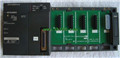
Program memory capacity: 8k.
Input / out
MITSUBISHI
Network module
A1SJ71BR11
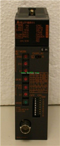
3C-2V/5C-2V coaxial cale etween the si
MITSUBISHI
CPU component
A1SHCPU
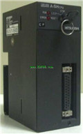
I/O control method: refresh mode or dire
MITSUBISHI
Temperature control module
A1S64TCTRT
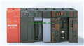
The most appropriate temperature regulat
Related download