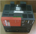
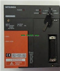
MITSUBISHI A173UHCPU Programming Manual A173UHCPU Common Instructions Manual
Product model: A173UHCPU
Name: Programmable Logic Controller
Brand: MITSUBISHI
Sort: Common Instructions Programming Manual
File language: English
Download link: MITSUBISHI A173UHCPU Programming Manual
Cable length: 20 meters.
For QCPU and GOT (need A9GT-QCNB) connection.
For the connection between GOT and GOT. Self service (IN, OUT): SI optical cable.
Other aspects (IN, OUT): SI optical cable.
Data link anomaly Bureau bypass.
Inter agency extension. RS-232 1 channels.
With DC input 2 points.
Transistor output 2 A173UHCPU Programming Manual .
Number of stations: 1 stops.
Station type: intelligent equipment station A173UHCPU
MITSUBISHI PLC online debugging.
On-line debugging is the process that will through the simulation debugging to further carry on the on-line unification to adjust.
On-line debugging process should be step by step,
From MITSUBISHI PLC only connected to the input device, and then connect the output device, and then connect to the actual load and so on and so on step by step A173UHCPU Programming Manual .
If you do not meet the requirements, the hardware and procedures for adjustment.
Usually only need to modify the part of the program can be.
MITSUBISHI PLC hardware implementation
Hardware implementation is mainly for the control cabinet and other hardware design and field construction.
Design control cabinet and the operating table and other parts of the electrical wiring diagram and wiring diagram A173UHCPU Programming Manual .
Electrical interconnection diagram of each part of the design system.
According to the construction drawings of the site wiring, and carry out a detailed inspection.
Because the program design and hardware implementation can be carried out at the same time,
So the design cycle of the MITSUBISHI PLC control system can be greatly reduced. Input type: DC input, negative public end.
Input points: 16 points.
Enter the response time: 1.5ms the following.
Rated input voltage / current: DC24V/6mA.
External connection: 3 wire.
Spring clamping terminal platform push type input module.
Input module with diagnostic function
The use of push type, do not need screw fastening, so can reduce the wiring hours.
Can be used for each 1 points to enter the wiring of the broken wire detection.
Wiring abnormality of external power supply can be confirmed.
Using 2 pieces of structure of the terminal units, maintenance can be maintained in the same line under the condition of the replacement module. 4 channel analog input module.
A1S64AD analog input module can accept the voltage or ccurrent signal,
The built-in microprocessor converts these signals to binary values,
For the control program to enjoy A173UHCPU Manual.
Signal can be instantaneous read, can also be programmed time / frequency average,
The offset and gain value can be set, and this component also includes the following performance:
4 input channels A173UHCPU Manual.
High resolution digital output.
Total accuracy plus or minus 1%.
Last one:
MITSUBISHI A2CCPUR21 Common Instructions Programming Manual
next one: MITSUBISHI A273UHCPU Common Instructions Programming Manual
next one: MITSUBISHI A273UHCPU Common Instructions Programming Manual
Related products
MITSUBISHI
General purpose CPU
Q13UDHCPU

Input / output points: 4096 points.
Num
Related download


