 LK Automation Limited
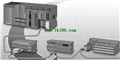
I/O MODULE AJ35PTF-24S Manual MITSUBISHI AJ35PTF-24S User's Manual
Product model: AJ35PTF-24S
Name: I/O MODULE
Brand: MITSUBISHI
Sort: User's Manual
File language: English
Download link: MITSUBISHI AJ35PTF-24S User's Manual
Screw terminal table type.
High precision / high resolution / high speed 2 piece type terminal.
Voltage / current input module.
Number of channels: 4 channels.
Number of stations: 1 stops.
Station type: remote equipment station.
MITSUBISHI PLC hardware implementation
Hardware implementation is mainly for the control cabinet and other hardware design and field construction AJ35PTF-24S Manual .
Design control cabinet and the operating table and other parts of the electrical wiring diagram and wiring diagram AJ35PTF-24S
Electrical interconnection diagram of each part of the design system.
According to the construction drawings of the site wiring, and carry out a detailed inspection.
Because the program design and hardware implementation can be carried out at the same time,
So the design cycle of the MITSUBISHI PLC control system can be greatly reduced AJ35PTF-24S Manual .
MITSUBISHI PLC online debugging.
On-line debugging is the process that will through the simulation debugging to further carry on the on-line unification to adjust.
On-line debugging process should be step by step,
From MITSUBISHI PLC only connected to the input device, and then connect the output device, and then connect to the actual load and so on and so on step by step AJ35PTF-24S Manual .
If you do not meet the requirements, the hardware and procedures for adjustment.
Usually only need to modify the part of the program can be. Input voltage range: DC24V MITSUBISHI AJ35PTF-24S User's Manual.
Output voltage: DC5V.
Output current: 2.5A.
I/O points is an important indicator of PLC.
Reasonable selection of I/O points can not only satisfy the control requirements of the system,
And the total investment of the system is the lowest MITSUBISHI AJ35PTF-24S User's Manual.
The input and output points and types of PLC should be determined according to the analog quantity and switch quantity of the controlled object,
Generally an input / output element to take up an input / output point MITSUBISHI AJ35PTF-24S User's Manual.
Taking into account the future adjustment and expansion,
In general should be estimated on the total number of points plus the amount of spare 20%~30%.
The following describes the centralized control system I/O points of the estimate.
Relay output interface circuit of PLC
Working process: when the internal circuit output digital signal 1,
There is a current flowing through, the relay coil has a current, and then the normally open contact is closed,
Provide load currennt and voltage AJ35PTF-24S .
When the internal circuit outputs a digital signal 0, there is no current flowing through it,
The relay coil does not have a current, and the normally open contact is broken off,
A current or voltage that is discoonnected from the load AJ35PTF-24S Manual .
It is through the output interface circuit to the internal digital circuit into a signal to make the load action or not action.
Related products
MITSUBISHI
DC input module
AJ35PJ-8D

DC input points: 8 points.
Input voltage
MITSUBISHI
DC input / transistor output module
AJ35PTF-56DT

DC input points: 32 points.
Input voltag
MITSUBISHI
Transistor output module
AJ35PJ-8T2

Output points: 8 points.
Output voltage
MITSUBISHI
DC input / silicon controlled output module
AJ35PTF-28DS
DC input points: 16 points.
Input voltag