 LK Automation Limited
AX40-UL Manual MITSUBISHI AX40-UL User's Manual
Product model: AX40-UL
Name: PLC
Brand: MITSUBISHI
Sort: User's Manual
File language: English
Download link: MITSUBISHI AX40-UL User's Manual
Output type: transistor output, drain type.
Output points: 32 points.
OFF leakage current: 0.1mA.
Output protection function: No.
Rated load voltage / current: DC12V/DC24V/0.5A.
External connection: 2 wire.
Spring clip terminal.
Do not need to be tightened further or locked with screws, which can reduce the working hours of wiring MITSUBISHI AX40-UL User's Manual.
Using 2 pieces of structure of the terminal units, maintenance can be maintained in the same line under the condition of the replacement module AX40-UL
When installing the module can choose to use the DIN guide rail or screw mounting.
Can be used for the 3 wire sensor input wiring. Multi axis positioning controller.
Optical data communication line.
Program capacity: Max 60K step MITSUBISHI AX40-UL User's Manual.
Input / output points: 1920 points.
The length of time required to execute the instruction, the length of the user''s program, the type of instruction, and the speed of the CPU execution are very significant,
Generally, a scanning process, the fault diagnosis time,
Communication time, input sampling and output refresh time is less,
The execution time is accounted for the vast majority of MITSUBISHI AX40-UL User's Manual.
The photoelectric coupler is composed of two luminous two extreme tubes and a photoelectric transistor.
Light emitting diode two: the input of a photo coupler and the change of electrical signal,
The light signal is generated by the light emitting diode, which is the same as the input signal.
The working process of the input interface circuit: when the switch is closed, the diode light,
The transistor is then guided to the internal circuit and input signal under the irradiation of the light.
When the switch is off, the diode does not emit light, and the transistor is not on the way. Internal circuit input signal.
It is through the input interface circuit to the external switch signal into PLC internal can accept the digital signal.
Photoelectric three levels: in the light of the light signal conduction, the degree of light signal and the intensity of the light signal.
The output signal has a linear relationship with the input signal in the linear operating region of the photoelectric coupler.
User program storage capacity: it is aa measure of how much the user application can store the number of indicators AX40-UL Manual.
Usually in words or K words as units. 16 bit binary number is a word,
Every 1024 words are 1K words. PLC to store instructions and data in words.
General llogical operation instructions each account for 1 words AX40-UL Manual. Timer / counter,
Shift instruction accounted for 2 words. Data operation instructions for 2~4.
Related products
MITSUBISHI
DC input / transistor output module
AX40Y50C
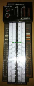
Input points: 16 points.
Input voltage a
MITSUBISHI
Input module
AX41
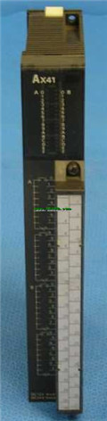
Input points: 32 points.
Voltage: DC12/2
MITSUBISHI
Input module
AX42
Enter points: 64 points.
Voltage: DC12/2
MITSUBISHI
Input module
AX40
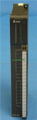
Input points: 16 points.
Voltage: DC12/2