 LK Automation Limited
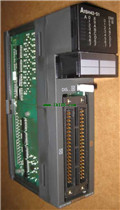
AD61-S1 Manual MITSUBISHI AD61-S1 User's Manual
Product model: AD61-S1
Name: High Speed Counter Module
Brand: MITSUBISHI
Sort: User's Manual
File language: English
Download link: MITSUBISHI AD61-S1 User's Manual
For A6TBXE/A6TBY36E/A6TBX54E/A6TBY54E/A6TBX70E (common cathode; source) long 3m.MELSECNET/MINI (-S3) data link system, A2C system transfer converter.
Plastic fiber cable -GI optical fiber cable.
MITSUBISHI PLC protection and chain procedures.
Protection and chain is an indispensable part of the program, must be carefully considered MITSUBISHI AD61-S1 User's Manual.
It can avoid the control logic confusion caused by illegal operations AD61-S1
MITSUBISHI PLC initialization procedure. After MITSUBISHI PLC on power, the general need to do some of the initial operation,
In order to start making necessary preparations, to avoid the wrong operation of the system.
The main contents of the initialization program are: to some data area, counter and so on,
Data needed to restore some of the data area,
Set or reset some relays,
For some initial state display, etc MITSUBISHI AD61-S1 User's Manual. .
MITSUBISHI PLC program simulation debugging
The basic idea of program simulation debugging is,
In order to facilitate the form of simulation to generate the actual state of the scene,
Create the necessary environmental conditions for the operation of the program.
Depending on the way the field signals are generated,
The simulation debugging has two forms of hardware simulation and software simulation MITSUBISHI AD61-S1 User's Manual. 2 channels.
4 wire platinum measuring antibodies (Pt100, JPt100).
Transform speed: 40ms/1 channel.
20 point terminal station.
The popularization and application of PLC programming has been developed rapidly in our country,
It has been widely used in all kinds of mechanical equipment and production process of electrical control devices,
All walks of life have emerged a large number of application of PLC transformation of the results of the equipment.
Understand the working principle of PLC, have the ability to design, debug and maintain the PLC control system,
Has become the basic requirements of modern industry for electrical technicians and engineering students.
PLC user program is designed according to the control system of the process control requirements,
PLC programming language through the preparation of specifications, in accordance with the actual needs of the use of the function to design.
As long as the user can master some kind of standard programming language,
To be able to use PLC in the control system,
To achieve a variety of automatic control functions.
The instruction list programming language is a programming language similar to assembly language mnemonic,
As well as assembly language by the operation code and the number of operations.
In the case of the computer for the PLC handheld programmer compile user program.
At the same time, the programming language of the instruction list corresponds to the ladder diagram programming language,
In PLC programming software can be converted to each other. Figure 3 is the instruction sheet corresponding to the ladder diagram of figure 2PLC.
The characteristics of instruction table programming language is used to represent mnemonic operation function,
Easy to remember, easy to grasp;
In the handheld programmer on the keyboard using the mnemonic representation, easy to operate, can be programmed in computer;
There is a one-to-one correspondence between the ladder diagram and the ladder diagram. Its characteristics are basically consistent with the ladder diagram language.
Functional block diagram language is a kind of PLC programming language, which is similar to digital logic circuit.
The function module is used to represent the function of the module,
Different function modules have different functions.
Functional module figure programming language features: functional block diagram programming language is characterized by a functional module for the unit,
Analysis and understanding of the control schheme is simple and easy: function module is to use graphical form of expression,
Intuitive, for a digital logic circuit based on the design of the staff is very easy to master the programming;
Control system with complex scale and coomplex control logic,
Because the function module diagram can clearly express the function relation, the programming debugging time is greatly reduced AD61-S1 Manual AD61-S1 Manual .
Related products
MITSUBISHI
Positioning module
AD71-S1
2 axes.
2 axis linear interpolation.
Con
MITSUBISHI
Input module
AX50-S1

Input points: 16 points.
Voltage: DC48V.
MITSUBISHI
Input / output module
A1SH42-S1
Enter 64 points.
Aove DC7V.
Response ti
MITSUBISHI
Motion controller (upgrade)
Q170MCPU-S1
Axis of control: 16.
Compact Q170MCPU in
Related download