 LK Automation Limited
A970GOT-TBD-CH User's Manual MITSUBISHI A970GOT-TBD-CH Hardware Manual
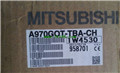
Product model: A970GOT-TBD-CH
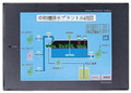
Name: Graphic Operation Terminal
Brand: MITSUBISHI
Sort: Hardware User's Manual
File language: English
Download link: MITSUBISHI A970GOT-TBD-CH User's Manual
8 channel analog input module.
This is a high density of 8 channel A/D components,
Can receive voltage and current input, with the installation of the inside of the cover plate switch,
The input type and range of each channel can be set up according to the application requirements:
12 bit resolution,
Automatic drift correction function,
0 MITSUBISHI A970GOT-TBD-CH Manual. 5msec/1 channel,
-10-0-10V or 0-20mA input A970GOT-TBD-CH Cable length: 30 meters.
For QnA/A/FX (FX1, FX2, FX2C) CPU and GOT connection between.
For connection between FA-CNV_CBL and GOT.
For connection between FX-2PIF and GOT.
For connection between FX-422AW0 and GOT.
For serial communication module AJ71QC24 (N) -R4 and GOT connection between.
For connection between AJ65BT-G4-S3 and GOT MITSUBISHI A970GOT-TBD-CH Manual. 8 slots.
Power supply unit.
QnAS series unit installation.
High speed access.
CE logo fit.
I/O points is an important indicator of PLC.
Reasonable selection of I/O points can not only satisfy the control requirements of the system,
And the total investment of the system is the lowest.
The input and output points and types of PLC should be determined according to the analog quantity and switch quantity of the controlled object,
Generally an input / output element to take up an input / output point MITSUBISHI A970GOT-TBD-CH Manual.
Taking into account the future adjustment and expansion,
In general should be estimated on the total number of points plus the amount of spare 20%~30%.
When the programmer input programinto the user program memory,
Then CPU according to the function of the system (the system program memory to explain the compiler),
Translate the user program into PLC internally recognized by the user to compile the program.
Relay output interface circuit of PLC
Working process: when the internal circuit output digital signal 1,
There is a current flowing through, the relay coil has a current, and then the normally open contact is closed,
Provide load current and volltage A970GOT-TBD-CH User's Manual.
When the internal circuit outputs a digital signal 0, there is no current flowing through it,
The relay coil does not have a current, and the normally open contact is broken off,
A current or voltage that is discoonnected from the load A970GOT-TBD-CH User's Manual.
It is through the output interface circuit to the internal digital circuit into a signal to make the load action or not action.
Last one:
MITSUBISHI A975GOT-TBD-CH Hardware User's Manual
next one: MITSUBISHI A975GOT-TBA-EU Hardware User's Manual
next one: MITSUBISHI A975GOT-TBA-EU Hardware User's Manual
Related products
MITSUBISHI
10 inch man machine interface
A970GOT-LBA
Series Name: A975GOT.
Size: 10 inches.
R
MITSUBISHI
10 inch man machine interface
A970GOT-SBD
Series Name: A975GOT.
Size: 10 inches.
R
Related download