 LK Automation Limited
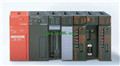
A1SX41 Manual MITSUBISHI I/O Module A1SX41 User's Manual
Product model: A1SX41
Name: I/O Module
Brand: MITSUBISHI
Sort: User's Manual
File language: English
Download link: MITSUBISHI A1SX41 User's Manual
8 channel analog output module.
Ans series has now launched a dedicated 8 channel D/A components,
Both voltage output and current output can be provided.
In this way, the user system to provide a higher density of D/A features,
The same method is used to maintain the same output voltage or current output MITSUBISHI I/O Module User's Manual. DC input points: 8 points.
Input voltage and current: 7mA, DC24V A1SX41
Input response time: 10ms.
8 point /1 a public side.
Positive / negative sharing.
Output points: 8 points.
Output voltage and current: DC24V/AC240V, 2A/1 point, 8A/1 common end.
Output response time: 12ms.
8 point /1 a public side.
Output form: relay.
40 point terminal station.
MITSUBISHI PLC protection and chain procedures MITSUBISHI I/O Module User's Manual.
Protection and chain is an indispensable part of the program, must be carefully considered.
It can avoid the control logic confusion caused by illegal operations.
MITSUBISHI PLC initialization procedure. After MITSUBISHI PLC on power, the general need to do some of the initial operation,
In order to start making necessary preparations, to avoid the wrong operation of the system.
The main contents of the initialization program are: to some data area, counter and so on,
Data needed to restore some of the data area,
Set or reset some relays,
For some initial state display, etc MITSUBISHI I/O Module User's Manual. .
MITSUBISHI PLC program simulation debugging
The basic idea of program simulation debugging is,
In order to facilitate the form of simulation to generate the actual state of the scene,
Create the necessary environmental conditions for the operation of the program A1SX41 User's Manual A1SX41 User's Manual.
Depending on the way the field signals are generated,
The simulation debugging has two forms of hardware simulation and software simulation. RS-232:1 channel, RS-422:1 channel.
BASIC program mode (A3MCPU corresponding): BASIC console interface to use A1SX41 User's Manual.
Sequential program mode (program controller CPU correspondence): non sequential computer connection interface and use.
How to choose MITSUBISHI PLC.
MITSUBISHI PLC options include the choice of MITSUBISHI PLC models, capacity, I/O module, power, etc..
MITSUBISHI PLC distribution I/O points and design MITSUBISHI PLC peripheral hardware circuit
Draw the I/O point of the PLC and the input / output device connection diagram or the corresponding table,
This part also can be carried out in second steps.
Design PLC peripheral hardwaree circuit A1SX41 Manual.
Draw the electrical wiring diagram of the other parts of the system,
Including the main circuit and the control circuit does not enter the PLC, etc..
The electrical schematic diagram of the system compoosed of I/O PLC connection diagram and PLC peripheral electrical circuit diagram MITSUBISHI I/O Module User's Manual.
So far the system''s hardware electrical circuit has been determined.
Related products

MITSUBISHI
32: terminal line adapter
A1S-TA32-7
32: terminal line adapter 0.75mm2 AGW18
MITSUBISHI
Input module
A1SX10
Input type: AC.
Input points: 16 points.
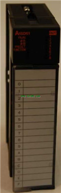
MITSUBISHI
High speed counting module
A1SD61
The A1SD61 high speed counting module ca