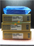
A0J2-E32D Manual MITSUBISHI Input/Output Module A0J2-E32D User's Manual
Product model: A0J2-E32D
Name: Input/Output Module
Brand: MITSUBISHI
Sort: User's Manual
File language: English
Download link: MITSUBISHI A0J2-E32D User's Manual
RS-232 1 channel.
RS-422/485 1 channel.
Transfer speed: 2 channels.
A total of 115.2kbps.
Input status and input information input from the input interface,
CPU will be stored in the working data memory or in the input image register.
And then combine the data and the program with CPU.
The result is stored in the output image register or the working data memory,
And then output to the output interface, control the external drive MITSUBISHI Input/Output Module User's Manual A0J2-E32D
Semiconductor circuit with memory function.
System program memory and user memory.
System program memory for storing system program,
Including management procedures, monitoring procedures, as well as the user program to do the compiler to compile the process of interpretation MITSUBISHI Input/Output Module User's Manual.
Read only memory. Manufacturers use, content can not be changed, power does not disappear. RS-232:1 channel, RS-422:1 channel.
BASIC program mode (A3MCPU corresponding): BASIC console interface to use.
Sequential program mode (program controller CPU correspondence): non sequential computer connection interface and use.
How to choose MITSUBISHI PLC.
MITSUBISHI PLC options include the choice of MITSUBISHI PLC models, capacity, I/O module, power, etc MITSUBISHI Input/Output Module User's Manual. .
MITSUBISHI PLC distribution I/O points and design MITSUBISHI PLC peripheral hardware circuit
Draw the I/O point of the PLC and the input / output device connection diagram or the corresponding table,
This part also can be carried out in second steps A0J2-E32D User's Manual.
Design PLC peripheral hardware circuit A0J2-E32D User's Manual.
Draw the electrical wiring diagram of the other parts of the system,
Including the main circuit and the control circuit does not enter the PLC, etc..
The electrical schematic diagram of the system composed of I/O PLC connection diagram and PLC peripheral electrical circuit diagram A0J2-E32D User's Manual.
So far the system''s hardware electrical circuit has been determined. MITSUBISHI PLC hardware implementation
Hardware implementation is mainly for the control cabinet and other hardware design and field construction.
Design control cabinet and the operating table and other parts of the electrical wiring diagram and wwiring diagram A0J2-E32D Manual.
Electrical interconnection diagram of each part of the design system.
According to the construction drawings of the site wiring, and carry out a detailed inspection.
Because the program deesign and hardware implementation can be carried out at the same time,
So the design cycle of the MITSUBISHI PLC control system can be greatly reduced MITSUBISHI Input/Output Module User's Manual.
Related products
MITSUBISHI
DC input / silicon controlled output module
A0J2-E28DS

Input points: 16 points.
Input voltage a
MITSUBISHI
AC input module
A0J2-E32A

Input points: 32 points.
Voltage: AC100
MITSUBISHI
CPU unit
A0J2CPU-DC24-S2

Input and output points: 480 points.
Pro

