Cable length: 10.6 meters.
Small CPU long distance connecting cable.
For QnAS/AnSCPU/ motion control and GOT connection.
For connection between A7GT-CNB and GOT.
Combination A8GT-EXCNB and A8GT-C_BS. Ethernet.
10BASE-T.
Remote I/O controller, coaxial cable.
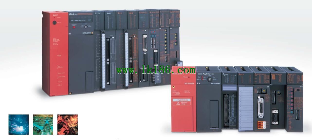
How to choose MITSUBISHI PLC AJ72BR15.
MITSUBISHI PLC options include the choice off MITSUBISHI PLC models, capacity, I/O module, power, etc..
MITSUBISHI PLC distribution I/O points and design MITSUBISHI PLC peripheral hardware circuit
Draw the I/O point of the PLC and the input / output device connection diagram or the corresponding table,
This part also can be carried out in second steps AJ72BR15.
Design PLC peripheral hardware circuit.
Draw the electrical wiring diagram of the other parts of the system,
Including the main circuit and the control circuit does not enter the PLC, etc AJ72BR15..
The electrical schematic diagram of the system composed of I/O PLC connection diagram and PLC peripheral electrical circuit diagram.
So far the system''s hardware electrical circuit has been determined. Fiber optic cable / twisted pair cable MITSUBISHI AJ72BR15.
Single bus.
Control unit.
According to the control requirements of the system, using the appropriate design method to design MITSUBISHI PLC program.
Procedures to meet the requirements of system control as the main line,
Write one by one to achieve the control function or the sub task of the program,
Gradually improve the functions specified by the system MITSUBISHI AJ72BR15.
MITSUBISHI PLC initialization procedure. After MITSUBISHI PLC on power, the general need to do some of the initial operation,
In order to start making necessary preparations, to avoid the wrong operation of the system MITSUBISHI AJ72BR15.
The main contents of the initialization program are: to some data area, counter and so on,
Data needed to restore some of the data area,
Set or reset some relays,
For some initial state display, etc.. The most appropriate temperature regulation control (PID control) is possible,
In order to control the PID does not need to specify a special command.
In addition, according to the automatic regulation function,
The automatic setting of PID number is possible.
The length of time required to execute the instruction, the length of the user''s program, the type of instruction, and the speed of the CPU execution are very significant,
Generally, a scanning process, the fault diagnosis time,
Communication time, input sampling and output refresh time is less,
The execution time is accounted for the vast majority of.
The response time of PLC is the interval between the time of the change of the external output signal of the PLC and the time of the change of the external output signal which is controlled by it,
Lag time, this is the time constant of the input circuit,
> The time constant of the output circuit, the arrangement of the user statement and the use of the instruction,
The cycle scan mode of PLC and the way of PLC to refresh the I/O and so on AJ72BR15.
This phenomenon is called the I/O delay time effect.
