 LK Automation Limited
RS-232:1 channel, RS-422:1 channel.
BASIC program mode (A3MCPU corresponding): BASIC console interface to use.
Sequential program mode (program controller CPU correspondence): non sequential computer connection interface and use.
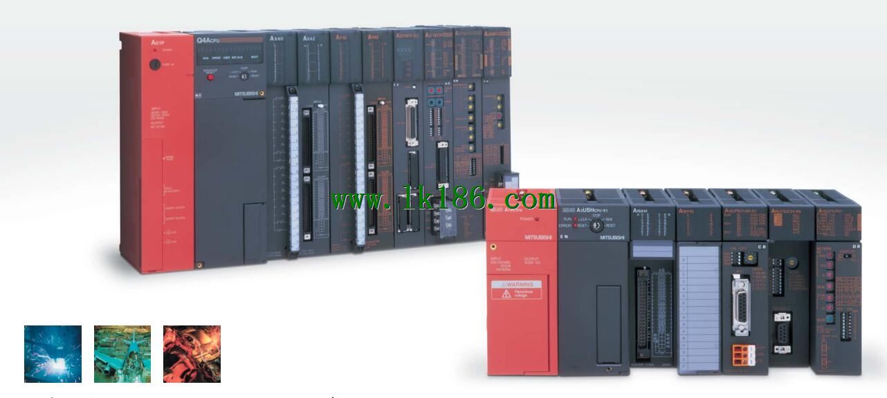
How to choose MITSUBISHI PLC.
MITSUBISHI PLC options include the choice of MITSUBISHI PLC models, capacity, I/O module, power, etc A6GPP..
MITSUBISHI PLC distribution I/O points and design MITSUBISHI PLC peripheral hardware circuit
Draw the I/O point of the PLC and the input / output device connection diagram or the corresponding table,
This part also can be carried out in second steps A6GPP.
Design PLC peripheral hardware circuit.
Draw the electrical wiring diagram of the other parts of the system,
Including the main circuit and the control circuit does not enter the PLC, etc A6GPP..
The electrical schematic diagram of the system composed of I/O PLC connection diagram and PLC peripheral electrical circuit diagram.
So far the system''s hardware electrical circuit has been determined.
A pack of 20.
Applicable models:
AJ65SBTC - - - type remote I/O module MITSUBISHI A6GPP.
AJ65VBTCU - - - type remote I/O module.
AJ65VBTCU- - type remote I/O module. 3C-2V/5C-2V coaxial cable.
Single bus.
PC inter network (management station / common station) / remote I/O network (remote control station).
How to choose MITSUBISHI PLC MITSUBISHI A6GPP.
MITSUBISHI PLC options include the choice of MITSUBISHI PLC models, capacity, I/O module, power, etc..
MITSUBISHI PLC distribution I/O points and design MITSUBISHI PLC peripheral hardware circuit
Draw the I/O point of the PLC and the input / output device connection diagram or the corresponding table,
This part also can be carried out in second steps MITSUBISHI A6GPP.
Design PLC peripheral hardware circuit.
Draw the electrical wiring diagram of the other parts of the system,
Including the main circuit and the control circuit does not enter the PLC, etc..
The electrical schematic diagram of the system composed of I/O PLC connection diagram and PLC peripheral electrical circuit diagram.
So far the system''s hardware electrical circuit has been determined. Screw, 2 piece type terminal
Thermocouple Input module.
Number of channels: 8 channels.
Number of stations: 4 stops.
Station type: remote equipment station.
MITSUBISHI PLC online debugging.
On-line debugging is the process that will through the simulation debugging to further carry on the on-line unification to adjust.
On-line debugging process should be step by step,
From MITSUBISHI PLC only connected to the input device, and then connect the output device, and then connect to the actual load and so on and so on step by step.
If you do not meet the requirements, the hardware and procedures for adjustment.
Usually only need to modify the part of the program can be.
MITSUBISHI PLC hardware implementation
Hardware implementation is mainly for the control cabinet and other hardware design and field construction.
Design control cabinet and the operating table and other parts of the electrical wiring diagram and wiring diagram.
Electrical interconnection diagram of each part of the design system.
According to the constructioon drawings of the site wiring, and carry out a detailed inspection A6GPP.
Because the program design and hardware implementation can be carried out at the same time,
So the design cycle of the MITSUBISHI PLC control system can be greatly reduced.