 LK Automation Limited
Pulse input: differential input.
Preset input: differential input.
Count range: 0~16777215.
Number of stations: 4 stops.
Station type: remote equipment station.
Configuration of master / local station,
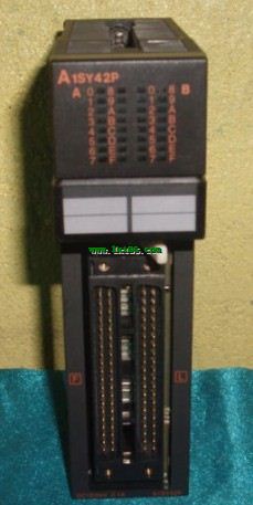
In addition to the other site network with different CC-Link in addition to the main station and the remote station configuration can also be the main statiion and the local station configuration A1SY42P.
A local PLC can communicate with the master station PLC and other remote workstations A1SY42P.
MITSUBISHI PLC hardware implementation
Hardware implementation is mainly for the control cabinet and other hardware design and field construction.
Design control cabinet and the operating table and other parts of the electrical wiring diagram and wiring diagram.
Electrical interconnection diagram of each part of the design system A1SY42P.
According to the construction drawings of the site wiring, and carry out a detailed inspection.
Because the program design and hardware implementation can be carried out at the same time,
So the design cycle of the MITSUBISHI PLC control system can be greatly reduced MITSUBISHI A1SY42P.
MITSUBISHI PLC online debugging.
On-line debugging is the process that will through the simulation debugging to further carry on the on-line unification to adjust.
On-line debugging process should be step by step,
From MITSUBISHI PLC only connected to the input device, and then connect the output device, and then connect to the actual load and so on and so on step by step MITSUBISHI A1SY42P.
If you do not meet the requirements, the hardware and procedures for adjustment.
Usually only need to modify the part of the program can be. A1ST60 analog timer module has 8 analog timers MITSUBISHI A1SY42P.
Each timer can be set between 0.1-600S,
Its accuracy plus or minus 2%.
Dial setting on the timing constant panel of the timer,
With a small screwdriver can be easily adjusted.
AnS, QnAS bus connection, the reader to write program 2 channel connection.
Input status and input information input from the input interface,
CPU will be stored in the working data memory or in the input image register.
And then combine the data and the program with CPU.
The result is stored in the output image register or the working data memory,
And then output to the output interface, control the external drive.
The response time of PLC is the interval between the time of the change of the external output signal of the PLC and the time of the change of the external output signal which is controlled by it,
Lag time, this is the time constant of the input circuit,
> The time constant of the output circuit, the arrangement of the user statement and the use of the instruction,
The cycle scan mode of PLC and the way of PLC to refresh the I/O and so on A1SY42P.
This phenomenon is called the I/O delay time effect.