 LK Automation Limited
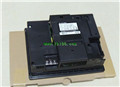
MITSUBISHI A975GOT-TBD User's Manual A975GOT-TBD Manual
Product model: A975GOT-TBD
Name: touch screen
Brand: MITSUBISHI
Sort: User's Manual
File language: English
Download link: MITSUBISHI A975GOT-TBD User's Manual
Bus connection.
Program 1 channel connection.
MITSUBISHI PLC detection, fault diagnosis and display and other procedures.
These procedures are relatively independent, generally in the basic completion of the program design and then add.
MITSUBISHI PLC protection and chain procedures.
Protection and chain is an indispensable part of the program, must be carefully considered A975GOT-TBD User's Manual A975GOT-TBD
It can avoid the control logic confusion caused by illegal operations. CC-Link master / slave station.
PLC is the use of " sequential scanning, and constantly circulating " way to work.
That is, in the operation of CPU, PLC according to the user according to the control requirements of the coexistence of the user in the memory of the program,
According to the instruction sequence number (or address number) for periodic cyclic scan, such as no jump instruction,
From the first instruction to the user program execution sequence one by one, until the end of the program,
And then return to the first command, start the next round of the new scan, in the process of each scan,
Also complete the sampling of the input signal and the output status of the refresh and other work A975GOT-TBD User's Manual A975GOT-TBD User's Manual.
PLC is the use of " sequential scanning, and constantly circulating " way to work.
That is, in the operation of CPU, PLC according to the user according to the control requirements of the coexistence of the user in the memory of the program,
According to the instruction sequence number (or address number) for periodic cyclic scan, such as no jump instruction,
From the first instruction to the user program execution sequence one by one, until the end of the program,
And then return to the first command, start the next round of the new scan, in the process of each scan,
Also complete the sampling of the input signal and the output status of the refresh and other work. 5 slots.
Can be installed in the power supply unit for A series units installed QnA/.
Relay output interface circuit of PLC
Working process: when the internal circuit output digital signal 1,
There is a current flowing through, the relay coil has a current, and then the normally open contact is closed,
Provide load current and voltage.
When the internal circuit outputs a digital signal 0, there is no current flowing through it,
The relay coil does not have a current, and the normally open contact is broken off,
A current or voltage that is disconnected from the load.
It is through the output interface circuit to the internal digital circuit into a signal to make the load action or not action.
I/O points is an important indicator of PLC.
Reasonable selection of I/O points can not only satisfy the control requirements of the system,
And the total investment of the system is the lowest.
The input and output points and types of PLC should be determined accordding to the analog quantity and switch quantity of the controlled object,
Generally an input / output element to take up an input / output point A975GOT-TBD Manual.
Taking into account the future adjustment and expansion,
In general should be estimaated on the total number of points plus the amount of spare 20%~30% A975GOT-TBD Manual.
The following describes the centralized control system I/O points of the estimate.
Related products
MITSUBISHI
12 inch man machine interface
A985GOT-TBD
Series Name: A985GOT.
Size: 12 inches.
R
MITSUBISHI
7 inch man machine interface
A956WGOT-TBD
Series Name: A956WGOT.
Size: 7 inches.
R
MITSUBISHI
6 inch man machine interface
A956GOT-TBD
Series Name: A956GOT.
Size: 6 inches.
Re
Related download