 LK Automation Limited
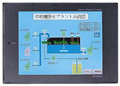
MITSUBISHI A975GOT-TBA-B User's Manual A975GOT-TBA-B Hardware Manual
Product model: A975GOT-TBA-B
Name: Graphic Operation Terminal
Brand: MITSUBISHI
Sort: Hardware User's Manual
File language: English
Download link: MITSUBISHI A975GOT-TBA-B User's Manual
Output type: transistor output, drain type.
Output points: 8 points.
OFF leakage current: 0.1mA.
Output protection function.
Rated load voltage / current: DC24V/DC24V/0.1A.
External connection: 2 wire.
Sensor connector type (E-CON type).
Using industry standard E-CON type.
Simple wiring through sensor connector A975GOT-TBA-B User's Manual.
When installing the module can choose to use the DIN guide rail or screw mounting A975GOT-TBA-B
3 wire sensor input. SRAM PC card.
Applicable models: A95_GOT (-M3) /A956WGOT. "Program memory capacity: 8k.
Input / output points: maximum 256 points.
A scan cycle of PLC must pass through three stages: input sampling, program execution and output refresh.
PLC in the input sampling phase: first of all, in order to scan the sequence of all existing input latches in the input terminal of the state or input data read,
And write it into the corresponding input status register,
Refresh the input, then close the input port, enter the program execution stage A975GOT-TBA-B User's Manual. Input type: DC input, positive common end.
Input points: 8 points.
Enter the response time: 1.5ms the following.
Rated input voltage / current: DC24V/5mA A975GOT-TBA-B User's Manual.
Output form: transistor output, leakage type.
Output points: 8 points.
OFF leakage current: 0.25mA.
Output protection function.
Rated load voltage / current: DC24V/0.5A.
External connection: 4 wire.
Fast connector type.
Simple wiring through quick connector.
Can be installed along the 6 direction.
MITSUBISHI PLC program simulation debugging
The basic idea of program simulation debugging is,
In order to facilitate the form of simulation to generate the actual state of the scene,
Create the necessary environmental conditions for the operation of the program.
Depending on the way the field signals are generated,
The simulation debugging has two forms of hardware simulation and software simulation. Number of channels: 2 channels.
Input signal: DC5/12/24, 2 to 5mA.
Counter: 10KPPS/1 with the highest frequency.
A1SD62, A1SD62D and A1SD62E are 2 channel high speed counter components for AnS series PLC.
They are improved in comparison with A1SD61 in the following ways: the density of channels.
In order to require a higher resolution and operating speed of the application to provide a higher count rate, reduce costs.
The instruction list programming language is a programming language similar to assembly language mnemonic,
As well as assembly language by the operation code and the number of operations.
In the case of the computer for the PLC handheld programmer compile user program.
At the same time, the programming language of the instruction list corresponds to the ladder diagram programming language,
In PLC programming software can be converted to each other. Figure 3 is the instruction sheet corresponding to the ladder diagram of figure 2PLC.
The characteristics of instruction table programming language is used to represent mnemonic operation function,
Easy to remember, easy to grasp;
In the handheld programmer on the keyboard using the mnemonic representation, easy to operate, can be programmed in computer;
There is a one-to-one correspondence between the ladder diagram and the ladder diagram. Its characteristics are basically consistent with the ladder diagram language.
Functional block diagram language is a kind of PLC programming language, which is similar to digital logic circuit.
The function module is used to represent the function of the module,
Different function modules have different functions.
Functional module figure programming language features: functional block diagram programming language is characterized by a functional module for the unit,
Analysis and understanding of the control scheme is simple and easy: function module is to use graphical form of expression,
Intuitive, for a digital logic circuit based on the design of the staff is very easy to master the programming;
Control system with complex scale and complex control logic,
Because the function module diagram can clearly express the function relation, the programming debugging time is greatly reduced.
The popularization and application of PLC programming has been developed rapidly in our country,
It has been widely used in all kinds of mechanical equipment and production process of electrical control devices,
All walks of life have emerged a large number of application of PLC transformation of the results of the equipment.
Understand the working principle of PLC, have the ability to design, debug and maintain the PLC control system,
Has become the basic requirements of modern industry for electrical technicians and engineering students.
PLC user program is designed accordding to the control system of the process control requirements,
PLC programming language through the preparation of specifications, in accordance with the actual needs of the use of the function to design A975GOT-TBA-B Manual.
As long as the user caan master some kind of standard programming language,
To be able to use PLC in the control system,
To achieve a variety of automatic control functions A975GOT-TBA-B Manual.
Output points: 8 points.
OFF leakage current: 0.1mA.
Output protection function.
Rated load voltage / current: DC24V/DC24V/0.1A.
External connection: 2 wire.
Sensor connector type (E-CON type).
Using industry standard E-CON type.
Simple wiring through sensor connector A975GOT-TBA-B User's Manual.
When installing the module can choose to use the DIN guide rail or screw mounting A975GOT-TBA-B
3 wire sensor input. SRAM PC card.
Applicable models: A95_GOT (-M3) /A956WGOT. "Program memory capacity: 8k.
Input / output points: maximum 256 points.
A scan cycle of PLC must pass through three stages: input sampling, program execution and output refresh.
PLC in the input sampling phase: first of all, in order to scan the sequence of all existing input latches in the input terminal of the state or input data read,
And write it into the corresponding input status register,
Refresh the input, then close the input port, enter the program execution stage A975GOT-TBA-B User's Manual. Input type: DC input, positive common end.
Input points: 8 points.
Enter the response time: 1.5ms the following.
Rated input voltage / current: DC24V/5mA A975GOT-TBA-B User's Manual.
Output form: transistor output, leakage type.
Output points: 8 points.
OFF leakage current: 0.25mA.
Output protection function.
Rated load voltage / current: DC24V/0.5A.
External connection: 4 wire.
Fast connector type.
Simple wiring through quick connector.
Can be installed along the 6 direction.
MITSUBISHI PLC program simulation debugging
The basic idea of program simulation debugging is,
In order to facilitate the form of simulation to generate the actual state of the scene,
Create the necessary environmental conditions for the operation of the program.
Depending on the way the field signals are generated,
The simulation debugging has two forms of hardware simulation and software simulation. Number of channels: 2 channels.
Input signal: DC5/12/24, 2 to 5mA.
Counter: 10KPPS/1 with the highest frequency.
A1SD62, A1SD62D and A1SD62E are 2 channel high speed counter components for AnS series PLC.
They are improved in comparison with A1SD61 in the following ways: the density of channels.
In order to require a higher resolution and operating speed of the application to provide a higher count rate, reduce costs.
The instruction list programming language is a programming language similar to assembly language mnemonic,
As well as assembly language by the operation code and the number of operations.
In the case of the computer for the PLC handheld programmer compile user program.
At the same time, the programming language of the instruction list corresponds to the ladder diagram programming language,
In PLC programming software can be converted to each other. Figure 3 is the instruction sheet corresponding to the ladder diagram of figure 2PLC.
The characteristics of instruction table programming language is used to represent mnemonic operation function,
Easy to remember, easy to grasp;
In the handheld programmer on the keyboard using the mnemonic representation, easy to operate, can be programmed in computer;
There is a one-to-one correspondence between the ladder diagram and the ladder diagram. Its characteristics are basically consistent with the ladder diagram language.
Functional block diagram language is a kind of PLC programming language, which is similar to digital logic circuit.
The function module is used to represent the function of the module,
Different function modules have different functions.
Functional module figure programming language features: functional block diagram programming language is characterized by a functional module for the unit,
Analysis and understanding of the control scheme is simple and easy: function module is to use graphical form of expression,
Intuitive, for a digital logic circuit based on the design of the staff is very easy to master the programming;
Control system with complex scale and complex control logic,
Because the function module diagram can clearly express the function relation, the programming debugging time is greatly reduced.
The popularization and application of PLC programming has been developed rapidly in our country,
It has been widely used in all kinds of mechanical equipment and production process of electrical control devices,
All walks of life have emerged a large number of application of PLC transformation of the results of the equipment.
Understand the working principle of PLC, have the ability to design, debug and maintain the PLC control system,
Has become the basic requirements of modern industry for electrical technicians and engineering students.
PLC user program is designed accordding to the control system of the process control requirements,
PLC programming language through the preparation of specifications, in accordance with the actual needs of the use of the function to design A975GOT-TBA-B Manual.
As long as the user caan master some kind of standard programming language,
To be able to use PLC in the control system,
To achieve a variety of automatic control functions A975GOT-TBA-B Manual.
Last one:
MITSUBISHI A970GOT-TBA-B Hardware User's Manual
next one: MITSUBISHI A975GOT-TBD-B Hardware User's Manual
next one: MITSUBISHI A975GOT-TBD-B Hardware User's Manual
Related products
MITSUBISHI
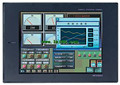
10 inch man machine interface
A970GOT-TBA-B
Series Name: A975GOT.
Size: 10 inches.
R

MITSUBISHI
10 inch man machine interface
A975GOT-TBA-EU
Series Name: A975GOT.
Size: 10 inches.
R
Related download