 LK Automation Limited
MITSUBISHI A970GOT-TBA-B User's Manual A970GOT-TBA-B Connection System Manual Manual
Product model: A970GOT-TBA-B
Name: touch screen
Brand: MITSUBISHI
Sort: Connection System Manual User's Manual
File language: English
Download link: MITSUBISHI A970GOT-TBA-B User's Manual
The main unit of the AS-i system
The response time of PLC is the interval between the time of the change of the external output signal of the PLC and the time of the change of the external output signal which is controlled by it,
Lag time, this is the time constant of the input circuit,
The time constant of the output circuit, the arrangement of the user statement and the use of the instruction,
The cycle scan mode of PLC and the way of PLC to refresh the I/O and so on A970GOT-TBA-B User's Manual A970GOT-TBA-B
This phenomenon is called the I/O delay time effect.
Input status and input information input from the input interface,
CPU will be stored in the working data memory or in the input image register.
And then combine the data and the program with CPU A970GOT-TBA-B User's Manual.
The result is stored in the output image register or the working data memory,
And then output to the output interface, control the external drive. 3C-2V/5C-2V coaxial cable.
Double loop.
PC inter network (management station / common station) / remote I/O network (remote control station).
How to choose MITSUBISHI PLC.
MITSUBISHI PLC options include the choice of MITSUBISHI PLC models, capacity, I/O module, power, etc A970GOT-TBA-B User's Manual. .
MITSUBISHI PLC distribution I/O points and design MITSUBISHI PLC peripheral hardware circuit
Draw the I/O point of the PLC and the input / output device connection diagram or the corresponding table,
This part also can be carried out in second steps.
Design PLC peripheral hardware circuit.
Draw the electrical wiring diagram of the other parts of the system,
Including the main circuit and the control circuit does not enter the PLC, etc..
The electrical schematic diagram of the system composed of I/O PLC connection diagram and PLC peripheral electrical circuit diagram.
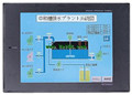
So far the system''s hardware electrical circuit has been determined. Series Name: A956GOT.
Size: 6 inches.
Resolution: 320 * 240.
Display device: STN color display.
Display color: 8 color.
Power supply: DC24V.
Memory card: 3M.
The external model design model of creating the system function is mainly to consider the data structure, the overall structure and the process description of the software,
The interface design is usually only used as accessories, only on the user''s situation (including age, gender, mental status, education level, personality, ethnic background and etc.) to understand, to design an effective user interface;
According to the user model of the future system of the end user (for short),
In the end, it is consistent with the system image (external characteristic) of the system after the system is rrealized,
Users can be satisfied with the system and be able to use it effectively;
When the user model is established, the information given by the system should be considered,
System mapping must accurately reflect the syntax and semantic information of the system A970GOT-TBA-B Manual A970GOT-TBA-B Manual.
In short, only to understand the user, to understand the task in order to design a good man-machine interface.
The response time of PLC is the interval between the time of the change of the external output signal of the PLC and the time of the change of the external output signal which is controlled by it,
Lag time, this is the time constant of the input circuit,
The time constant of the output circuit, the arrangement of the user statement and the use of the instruction,
The cycle scan mode of PLC and the way of PLC to refresh the I/O and so on A970GOT-TBA-B User's Manual A970GOT-TBA-B
This phenomenon is called the I/O delay time effect.
Input status and input information input from the input interface,
CPU will be stored in the working data memory or in the input image register.
And then combine the data and the program with CPU A970GOT-TBA-B User's Manual.
The result is stored in the output image register or the working data memory,
And then output to the output interface, control the external drive. 3C-2V/5C-2V coaxial cable.
Double loop.
PC inter network (management station / common station) / remote I/O network (remote control station).
How to choose MITSUBISHI PLC.
MITSUBISHI PLC options include the choice of MITSUBISHI PLC models, capacity, I/O module, power, etc A970GOT-TBA-B User's Manual. .
MITSUBISHI PLC distribution I/O points and design MITSUBISHI PLC peripheral hardware circuit
Draw the I/O point of the PLC and the input / output device connection diagram or the corresponding table,
This part also can be carried out in second steps.
Design PLC peripheral hardware circuit.
Draw the electrical wiring diagram of the other parts of the system,
Including the main circuit and the control circuit does not enter the PLC, etc..
The electrical schematic diagram of the system composed of I/O PLC connection diagram and PLC peripheral electrical circuit diagram.
So far the system''s hardware electrical circuit has been determined. Series Name: A956GOT.
Size: 6 inches.
Resolution: 320 * 240.
Display device: STN color display.
Display color: 8 color.
Power supply: DC24V.
Memory card: 3M.
The external model design model of creating the system function is mainly to consider the data structure, the overall structure and the process description of the software,
The interface design is usually only used as accessories, only on the user''s situation (including age, gender, mental status, education level, personality, ethnic background and etc.) to understand, to design an effective user interface;
According to the user model of the future system of the end user (for short),
In the end, it is consistent with the system image (external characteristic) of the system after the system is rrealized,
Users can be satisfied with the system and be able to use it effectively;
When the user model is established, the information given by the system should be considered,
System mapping must accurately reflect the syntax and semantic information of the system A970GOT-TBA-B Manual A970GOT-TBA-B Manual.
In short, only to understand the user, to understand the task in order to design a good man-machine interface.
Last one:
MITSUBISHI A960GOT-EBD Connection System Manual User's Manual
next one: MITSUBISHI A985GOT-TBD-V Connection System Manual User's Manual
next one: MITSUBISHI A985GOT-TBD-V Connection System Manual User's Manual
Related products
MITSUBISHI
10 inch man machine interface
A970GOT-TBD-B
Series Name: A975GOT.
Size: 10 inches.
R
MITSUBISHI
10 inch man machine interface
A970GOT-SBA
Series Name: A975GOT.
Size: 10 inches.
R
MITSUBISHI
10 inch man machine interface
A970GOT-TBA-EU
Series Name: A975GOT.
Size: 10 inches.
R
MITSUBISHI
10 inch man machine interface
A970GOT-SBD
Series Name: A975GOT.
Size: 10 inches.
R
Related download