 LK Automation Limited
MITSUBISHI A1SJ71C24-R2 User's Manual A1SJ71C24-R2 Hardware Manual
Product model: A1SJ71C24-R2
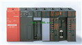
Name: Computer link Module
Brand: MITSUBISHI
Sort: Hardware User's Manual
File language: English
Download link: MITSUBISHI A1SJ71C24-R2 User's Manual
Multiple CPU units for A3VTS multiplex system.
Modular: PLC is the basic components of a separate module.
Medium and large PLC used this way. Easy maintenance.
User program storage capacity: it is a measure of how much the user application can store the number of indicators.
Usually in words or K words as units A1SJ71C24-R2 User's Manual. 16 bit binary number is a word,
Every 1024 words are 1K words A1SJ71C24-R2 PLC to store instructions and data in words.
General logical operation instructions each account for 1 words. Timer / counter,
Shift instruction accounted for 2 words. Data operation instructions for 2~4.
Relay output interface circuit of PLC
Working process: when the internal circuit output digital signal 1,
There is a current flowing through, the relay coil has a current, and then the normally open contact is closed,
Provide load current and voltage A1SJ71C24-R2 User's Manual.
When the internal circuit outputs a digital signal 0, there is no current flowing through it,
The relay coil does not have a current, and the normally open contact is broken off,
A current or voltage that is disconnected from the load.
It is through the output interface circuit to the internal digital circuit into a signal to make the load action or not action A1SJ71C24-R2 User's Manual. AnS, QnAS bus connection, the reader to write program 1 channel connection.
Input status and input information input from the input interface,
CPU will be stored in the working data memory or in the input image register.
And then combine the data and the program with CPU.
The result is stored in the output image register or the working data memory,
And then output to the output interface, control the external drive.
The response time of PLC is the interval between the time of the change of the external output signal of the PLC and the time of the change of the external output signal which is controlled by it,
Lag time, this is the time constant of the input circuit,
The time constant of the output circuit, the arrangement of the user statement and the use of the instruction,
The cycle scan mode of PLC and the way of PLC to refresh the I/O and so on.
This phenomenon is called the I/O delay time effect. 32: terminal line adapter 0.75mm2 (AGW18).Series Name: A985GOT.
Size: 12 inches.
Resolution: 800 * 600.
Display equipment: high brightness TFT color display.
Display color: 256 color.
Power supply: AC100-240V.
Authentication: UL/cUL/CE.
Man machine interface (Machine Interaction Human, referred to as HMI), also known as the user interface or user interface,
Is a communicaation interface between human and computer,
Is an important part of the computer system A1SJ71C24-R2 Manual .
Is a medium for interaction and information exchange between the system and the user,
It realizes the transformation between the internal fform of information and the acceptable form of human being A1SJ71C24-R2 Manual .
Where there is a man-machine interface in the field of human computer information exchange.
Last one:
MITSUBISHI A1SJ71UC24-R2 Hardware User's Manual
next one: MITSUBISHI A1SJ71UC24-PRF Hardware User's Manual
next one: MITSUBISHI A1SJ71UC24-PRF Hardware User's Manual
Related products
MITSUBISHI
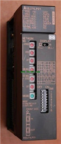
Melsecnet module
A1SJ71LP21

10Mps transmission speed, the computer
MITSUBISHI
Ethernet module
A1SJ71E71N-B2

10BASE2.
PLC is introduced y the relay
MITSUBISHI
Network module
A1SJ71QLR21
3C-2V/5C-2V coaxial cale etween doule
MITSUBISHI
Melsecnet module
A1SJ71LP21GE
Using A1SJ71LP21 and A1SJ71BR11MELSECNET