 LK Automation Limited
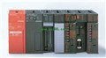
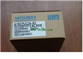
MITSUBISHI A1SCPUC24-R2 User's Manual A1SCPUC24-R2 Manual
Product model: A1SCPUC24-R2
Name: Computer Link Module
Brand: MITSUBISHI
Sort: User's Manual
File language: English
Download link: MITSUBISHI A1SCPUC24-R2 User's Manual
Input and output points: 480 points.
Program capacity: 7K step.
Basic command processing speed: 4.4 ~ 5.6us.
Power supply: input AC100 ~ 120/200 ~ 240V/ output 2A DC24V, 0.5A DC5V.
Modular: PLC is the basic components of a separate module.
Medium and large PLC used this way. Easy maintenance.
User program storage capacity: it is a measure of how much the user application can store the number of indicators A1SCPUC24-R2 User's Manual A1SCPUC24-R2
Usually in words or K words as units. 16 bit binary number is a word,
Every 1024 words are 1K words. PLC to store instructions and data in words.
General logical operation instructions each account for 1 words. Timer / counter,
Shift instruction accounted for 2 words. Data operation instructions for 2~4 A1SCPUC24-R2 User's Manual.
Relay output interface circuit of PLC
Working process: when the internal circuit output digital signal 1,
There is a current flowing through, the relay coil has a current, and then the normally open contact is closed,
Provide load current and voltage.
When the internal circuit outputs a digital signal 0, there is no current flowing through it,
The relay coil does not have a current, and the normally open contact is broken off,
A current or voltage that is disconnected from the load A1SCPUC24-R2 User's Manual.
It is through the output interface circuit to the internal digital circuit into a signal to make the load action or not action. Control axis number: 2 axes (independent, straight line arc interpolation at the same time)
Number of stations: 4 stops.
Station type: intelligent equipment station.
Configuration of master / local station,
In addition to the other site network with different CC-Link in addition to the main station and the remote station configuration can also be the main station and the local station configuration.
A local PLC can communicate with the master station PLC and other remote workstations.
MITSUBISHI PLC hardware implementation
Hardware implementation is mainly for the control cabinet and other hardware design and field construction.
Design control cabinet and the operating table and other parts of the electrical wiring diagram and wiring diagram.
Electrical interconnection diagram of each part of the design system.
According to the construction drawings of the site wiring, and carry out a detailed inspection.
Because the program design and hardware implementation can be carried out at the same time,
So the design cycle of the MITSUBISHI PLC control system can be greatly reduced.
MITSUBISHI PLC online debugging.
On-line debugging is the process that will through the simulation debugging to further carry on the on-linne unification to adjust A1SCPUC24-R2 Manual .
On-line debugging process should be step by step,
From MITSUBISHI PLC only connected to the input device, and then connect the output device, and then connect to the actual load and so on and so on stepp by step A1SCPUC24-R2 Manual .
If you do not meet the requirements, the hardware and procedures for adjustment.
Usually only need to modify the part of the program can be.
Related products
MITSUBISHI
Serial communication module
A1SJ71QC24-R2
RS-232 2 channel.
Transfer speed: 0.3-19
MITSUBISHI
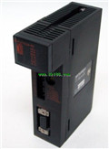
CPU component with built-in RS232C interface
A1SCPUC24-R2
A1SCPUC24-R2 integrates all functions of
MITSUBISHI
Serial communication module
RJ71C24-R2

230.4kps Max., RS-232 2 channel.
When u
Related download