 LK Automation Limited
AJ71C22 User's Manual MITSUBISHI AJ71C22 Manual
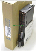
Product model: AJ71C22
Name: Multidrop link unit
Brand: MITSUBISHI
Sort: User's Manual
File language: English
Download link: MITSUBISHI AJ71C22 User's Manual
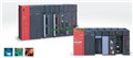
Multi axis positioning controller.
Optical data communication line.
Program capacity: Max 60K step.
Input / output points: 1920 points.
When the switch is off, the diode does not emit light, and the transistor is not on the way. Internal circuit input signal.
It is through the input interface circuit to the external switch signal into PLC internal can accept the digital signal MITSUBISHI AJ71C22 Manual AJ71C22
Photoelectric three levels: in the light of the light signal conduction, the degree of light signal and the intensity of the light signal.
The output signal has a linear relationship with the input signal in the linear operating region of the photoelectric coupler.
User program storage capacity: it is a measure of how much the user application can store the number of indicators MITSUBISHI AJ71C22 Manual .
Usually in words or K words as units. 16 bit binary number is a word,
Every 1024 words are 1K words. PLC to store instructions and data in words.
General logical operation instructions each account for 1 words. Timer / counter,
Shift instruction accounted for 2 words. Data operation instructions for 2~4.
The length of time required to execute the instruction, the length of the user''s program, the type of instruction, and the speed of the CPU execution are very significant,
Generally, a scanning process, the fault diagnosis time,
Communication time, input sampling and output refresh time is less,
The execution time is accounted for the vast majority of MITSUBISHI AJ71C22 Manual .
The photoelectric coupler is composed of two luminous two extreme tubes and a photoelectric transistor.
Light emitting diode two: the input of a photo coupler and the change of electrical signal,
The light signal is generated by the light emitting diode, which is the same as the input signal.
The working process of the input interface circuit: when the switch is closed, the diode light,
The transistor is then guided to the internal circuit and input signal under the irradiation of the light. DC input points: 32 points.
Input voltage and current: 3/7mA, DC12/24V.
Response time: 10ms.
Positive pole sharing.
16 point /1 a public side.
Output points: 24 points.
Output voltage and current: DC12/24V, 0.5A/1 point, 3.2A/1 common end.
Response time: 2ms.
8 point /1 a public end, 4 point /1 a public end.
Output form: transistor output, leakage type.
36 point terminal table * 2.
Number of stations: 8 stops.
Compact remote I/O unit.
According to the control requirements of the system, using the appropriate design method to design MITSUBISHI PLC program.
Procedures to meet the requirements of system control as the main line,
Write one by one to achieve the control function or the sub task of the program,
Gradually improve the functions specified by the system.
MITSUBISHI PLC detection, fault diagnosis and display and other procedures.
These procedures are relatively independent, generally in the basic completion of the program design and then add.
Hardware simulation method is to use a number of hardware equipment to simulate the generation of the signal,
The signals are connected to the input end of the PLC system in a hard wired way, and thee timeliness is strong AJ71C22 User's Manual.
Software simulation method is in the MITSUBISHI PLC in the preparation of a set of simulation program,
The simulation provides the field signal, which is simple and easy to operate, but it is not easy too guarantee the timeliness AJ71C22 User's Manual.
Simulation of the process of debugging, debugging method can be used to segment, and the monitoring function of programmer.
Related products
MITSUBISHI
Serial communication module
AJ71QC24N-R4
RS-422 1 channel, RS-422/485 1 channel.
MITSUBISHI
GI fiber optic cable module
AJ71LP21G
G1-50/125 fier optic cale.
Doule loop

MITSUBISHI
Computer link module
AJ71C24-S6
RS-232:1, RS-422/485:1.
Transmission spe